BE/HR
Deflagration Flame Arrester, endurance burning proof, End-of-Line

Features
Protección integral contra la intemperie
La caperuza con pantalla de protección protege la unidad apagallamas PROTEGO® frente a impactos ambientales, como nidos de animales y condiciones meteorológicas adversas
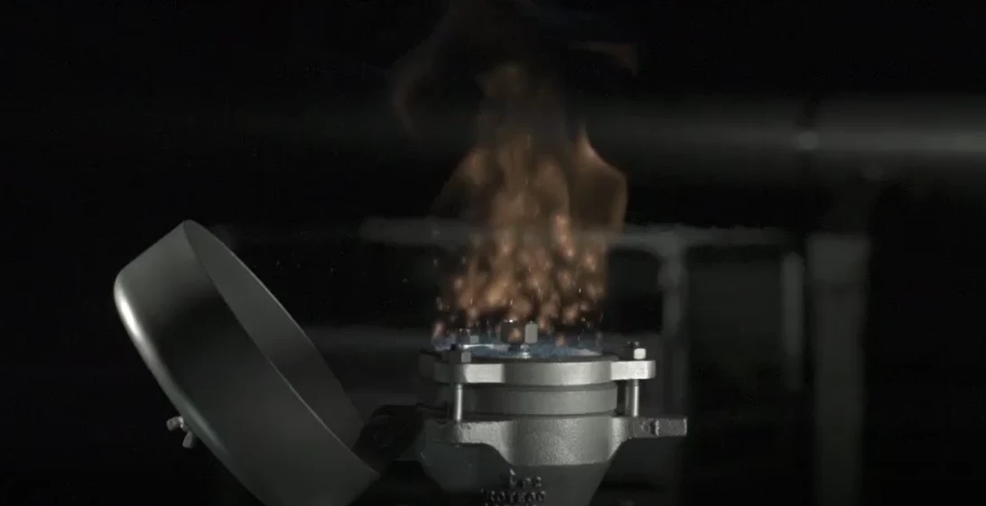
Indicación visible de fuego mediante inclinación de la caperuza protectora contra la intemperie
En caso de fuego, la caperuza se abre, permitiendo que la llama sea visible desde gran distancia
Seguridad contracombustión prolongada
Protección contra deflagraciones atmosféricas y combustión prolongada
Resistente a productos químicos
El elemento fusible, alineado en posición central, es resistente a los productos químicos
Diseño modular
Permite la sustitución y limpieza de los discos de filtro FLAMEFILTER® de forma individual
Piezas de recambio
Piezas de recambio eficientes en costes
Function and Description
Protection Against Atmospheric Deflagration and Endurance Burning
For many years the PROTEGO® BE/HR End-of-Line Deflagration Flame Arrester has been successfully used to protect vessels and process engineering apparatus which are not pressurized. The device provides protection against flame transmission through atmospheric deflagration and stabilized flames which can burn for very long time on the Flame Arrester Element surface, so called endurance burning. Main application area is on in- and out-breathing and vent lines, with the goal to prevent flame transmission caused by endurance burning or atmospheric deflagration from propagating into the vessel or plant.
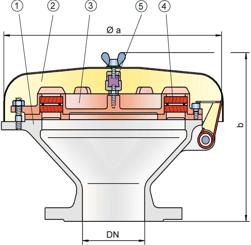
Main Component – PROTEGO® Flame Arrester Unit
The PROTEGO® BE/HR consists of a housing (1), a weather hood (2) and the PROTEGO® Flame Arrester Unit (3). During normal operation the metal weather hood is in a closed position. If a flame burns on the Flame Arrester Element surface, the fusible link (5), located in a center position, will melt and let the spring loaded weather hood move into the open position. The PROTEGO® Flame Arrester Unit consists of two FLAMEFILTER® discs (4), which are installed in a FLAMEFILTER® casing.

For Explosion Groups IIA to IIB3
The FLAMEFILTER® gap size will depend on the devices intended use. Detailing the operating conditions such as the temperature, explosion group and the composition of the fluid, enables PROTEGO® to select the best End-of-Line Deflagration Flame Arrester for your application. The PROTEGO® BE/HR Series End-of-Line Deflagration Flame Arrester is available for substances from explosion groups IIA to IIB3 (NEC groups D to C MESG ≥ 0.65 mm). In a modified design, this device is also available for Ethanol applications.
The standard design can be used with operating temperature of up to +60°C / 140°F.
Type-approved according to ATEX Directive as well as other international standards.
Product Data
Dimensiones
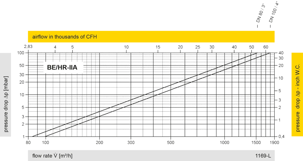
To select the nominal size (DN), please use the flow capacity charts on the following pages
| DN | 80 / 3" | 100 / 4" |
| a | 353 / 13.90 | 353 / 13.90 |
| b | 250 / 9.84 | 250 / 9.84 |
Dimensiones en mm / pulgadas
Dimensions for deflagration flame arrester with heating jacket upon request
Selección del grupo de explosión
| MESG | Expl. Gr. (IEC / CEN) | Gas Group (NEC) |
| > 0,90 mm | IIA | D |
| ≥ 0,65 mm | IIB3 | C |
Special approvals upon request
Selección de materiales para la vivienda
| Design | B | C |
| Housing | Steel | Stainless Steel |
| Weather hood | Steel | Stainless Steel |
| Flame arrester unit | A | A, C |
Special materials upon request
Combinación de materiales para la unidad apagallamas
| Design | A | C |
| FLAMEFILTER® cage | Stainless Steel | Stainless Steel |
| FLAMEFILTER® | Stainless Steel | Hastelloy |
| Spacer | Stainless Steel | Hastelloy |
Special materials upon request
Tipo de bridas de conexión
| EN 1092-1; Form B1 |
| ASME B16.5 CL 150 R.F. |
other connections upon request
Diagrama de flujo volumétrico

Los diagramas de flujo volumétrico han sido determinados con un banco de pruebas de caudal calibrado y certifi - cado por TÜV. El flujo volumétrico V. en [m³/h] y el CFH se refi eren a las condiciones estándar de referencia de aire según ISO 6358 (20°C, 1bar). La conversión a otras densidades y temperaturas están referidas en el Vol. 1: “Fundamentos Técnicos”.