DA-G
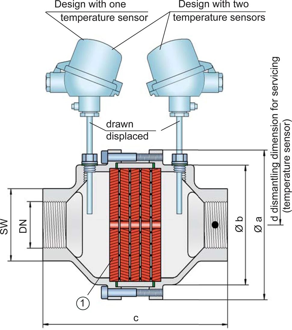
In-Line Detonation Flame Arrester for stable detonations and deflagrations in a straight through design, bidirectional

Features
Diseño modular
Direccional
Montaje y desmontaje más rápido
Opciones de aplicación versátiles
Posibilidad de instalar sensores de temperatura
Piezas de recambio
For Industrial Use in Gas Analysis Lines
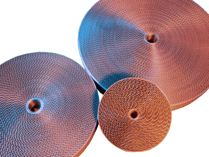
Main Component – PROTEGO® Flame Arrester Unit

Many Individual Certifications
Dimensiones
To select the nominal size (DN), please use the flow capacity charts on the following pages
| DN | G ½" | G ¾" | G 1" | G 1¼" | G 1½" | G 2" |
| a | 80 / 3.15 | 80 / 3.15 | 100 / 3.94 | 100 / 3.94 | 155 / 6.10 | 155 / 6.10 |
| b | 55 / 2.17 | 55 / 2.17 | 76 / 2.99 | 76 / 2.99 | 124 / 4.88 | 124 / 4.88 |
| c (IIA) | 112 / 4.41 | 112 / 4.41 | 122 / 4.80 | 122 / 4.80 | 205 / 8.07 | 205 / 8.07 |
| c (IIB3 and IIC) | 135 / 5.31 | 135 / 5.31 | 145 / 5.71 | 145 / 5.71 | 205 / 8.07 | 205 / 8.07 |
| d | — | — | — | — | 400 / 15.75 | 400 / 15.75 |
| SW | 32 / 1.26 | 32 / 1.26 | 50 / 1.97 | 50 / 1.97 | 75 / 2.95 | 75 / 2.95 |
Dimensions in mm / inches, SW= width across flats
Selección del grupo de explosión
| MESG | Expl. Gr. (IEC / CEN) | Gas Group (NEC) |
| > 0,90 mm | IIA | D |
| ≥ 0,65 mm | IIB3 | C |
| < 0,50 mm | IIC | B |
Special approvals upon request
Selección de la máxima presión de operación
| Expl. Gr. | DN | G ½" | G ¾" | G 1" | G 1¼" | G 1½" | G 2'' |
| IIA | Pmax | 1,2 / 17.4 | 1,2 / 17.4 | 1,1 / 15.9 | 1,1 / 15.9 | 1,1 / 15.9 | 1,1 / 15.9 |
| IIB3 | Pmax | 1,1 / 15.9 | 1,1 / 15.9 | 1,1 / 15.9 | 1,1 / 15.9 | 1,4 / 20.3 | 1,4 / 20.3 |
| IIC | Pmax | 1,1 / 15.9 | 1,1 / 15.9 | 1,1 / 15.9 | 1,1 / 15.9 | 1,6 / 23.2 | 1,6 / 23.2 |
Pmax = maximum allowable operating pressure in bar / psi absolute, higher operating pressure upon request
Especificación de la máx. temperatura de operación
| ≤ 60°C / 140°F | Tmaximum allowable operating temperature in °C |
| - | Designation |
higher operating temperatures upon request
Selección de materiales para la vivienda
| Design | B | C |
| Housing | Stainless Steel | Hastelloy |
| Gasket | PTFE | PTFE |
| FLAMEFILTER®* | Stainless Steel | Hastelloy |
* the FLAMEFILTER® are also available in the materials Tantalum, Inconel, Copper, etc. when the listed housing and cage materials are used.
Special materials upon request
Tipo de conexión
| Pipe thread DIN ISO 228-1 | DIN |
other types of thread upon request
Diagrama de flujo volumétrico
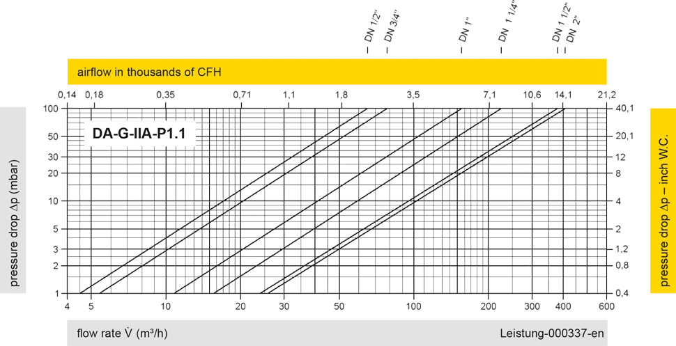
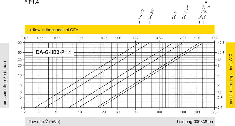
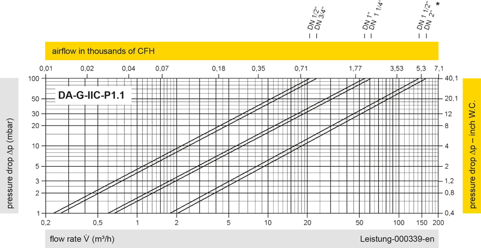
Los diagramas de flujo volumétrico han sido determinados con un banco de pruebas de caudal calibrado y certifi - cado por TÜV. El flujo volumétrico V. en [m³/h] y el CFH se refi eren a las condiciones estándar de referencia de aire según ISO 6358 (20°C, 1bar). La conversión a otras densidades y temperaturas están referidas en el Vol. 1: “Fundamentos Técnicos”.