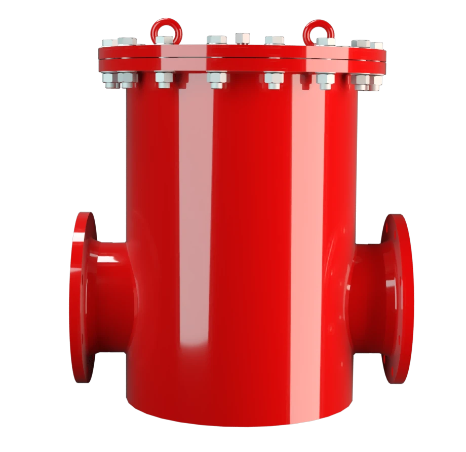
DV/ZT
Pressure and Vacuum Relief Valve, In-Line
Features
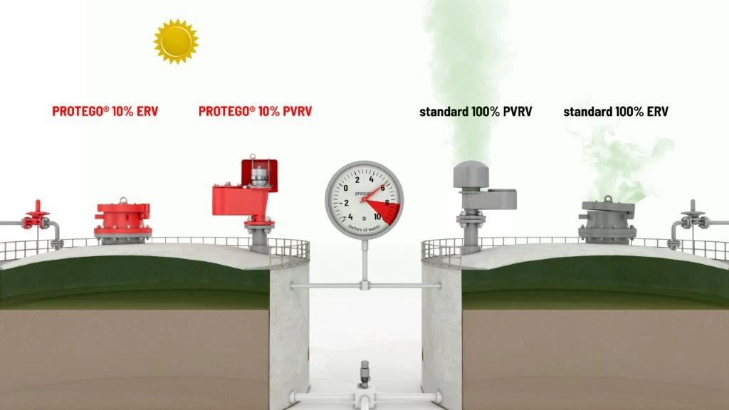
Tecnología del 10%
Extrema estanqueidad
Mantenimiento óptimo de la presión
Alta capacidad volumétrica
Se usa en zonas con riesgo de explosión
Diseño de cuerpo robusto
Pressure or Backflow Protection in Venting or Exhaust Lines
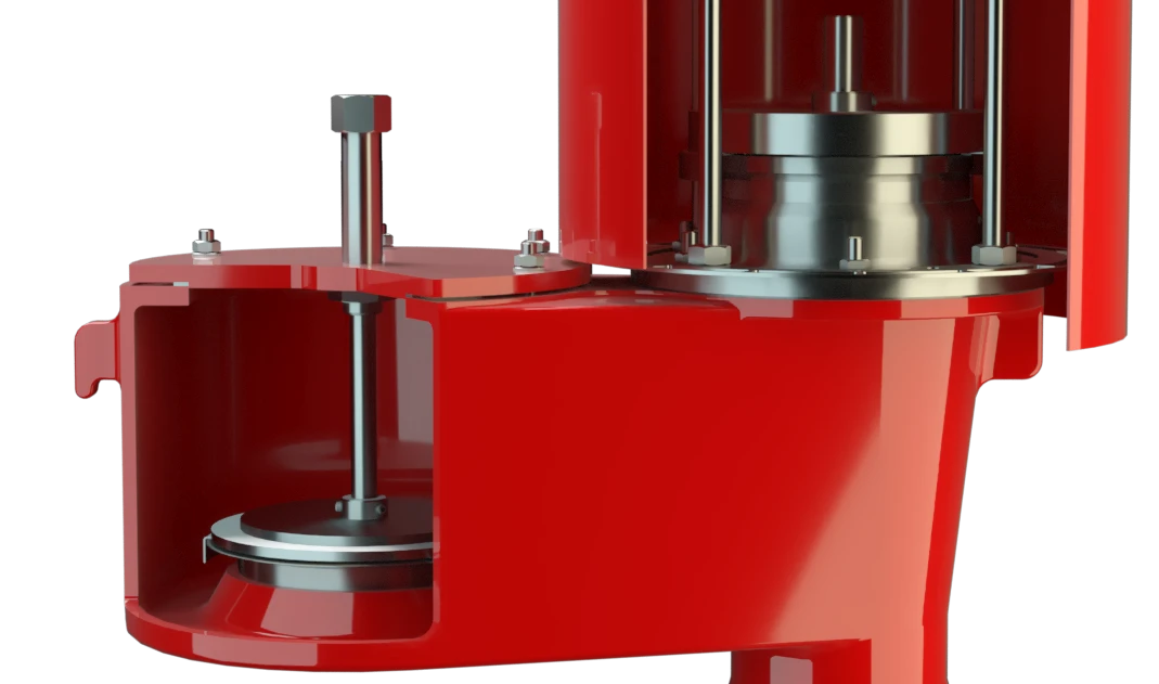
Full Lift Technology
Custom Materials
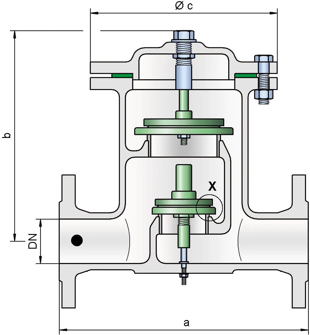
Dimensiones
To select the nominal size (DN), please use the flow capacity chart on the following page
| DN | 40 / 1½“ | 50 / 2" | 80 / 3" | 100 / 4" | 150 / 6" |
| a | 280 / 11.02 | 280 / 11.02 | 340 / 13.39 | 390 / 15.35 | 520 / 20.47 |
| b | 270 / 10.63 | 270 / 10.63 | 290 / 11.42 | 355 / 13.98 | 425 / 16.73 |
| c | 210 / 8.27 | 210 / 8.27 | 280 / 11.02 | 310 / 12.20 | 390 / 15.35 |
Dimensiones en mm / pulgadas
Larger sizes upon request
Dimensions for pressure and vacuum relief valve with heating jacket upon request
Selección de materiales para la vivienda
| Design | A | B |
| Housing | Steel | Stainless Steel |
| Heating jacket (DV / ZT-H-...) | Steel | Stainless Steel |
| Valve seat | Stainless Steel | Stainless Steel |
| Gasket | PTFE | PTFE |
Option: Housing with ECTFE-lining
Special materials upon request
Material selection for upper valve pallet
| Design | A | B | C | D |
| Pressure range [mbar] [inch W.C.] | ±2.0 up to ±3.5 ±0.8 up to ±1.4 | ±3.5 up to ±14 >±1.4 up to ±5.6 | ±14 up to ±60 >±5.6 up to ±24 | ±14 up to ±60 >±5.6 up to ±24 |
| Valve pallet | Aluminium | Stainless Steel | Stainless Steel | Stainless Steel |
| Sealing | FEP | FEP | Metal to Metal | PTFE |
Special materials upon request
For higher set pressure refer to type DV/ZT-F.
Material selection for lower valve pallet
| Design | A | B | C | D | E | F |
| Pressure range [mbar] [inch W.C.] | ±2,0 up to ±3,5 ±0.8 up to ±1.4 | ±3,5 up to ±14 ±1.4 up to ±5.6 | ±14 up to ±35 ±5.6 up to ±14 | ±35 up to ±50 ±14 up to ±20 | ±14 up to ±35 ±5.6 up to ±14 | ±35 up to ±50 ±14 up to ±20 |
| Valve pallet | Aluminium | Stainless Steel | Stainless Steel | Stainless Steel | Stainless Steel | Stainless Steel |
| Sealing | FEP | FEP | Metal to Metal | Metal to Metal | PTFE | PTFE |
Special materials and lower set vacuum upon request
Tipo de bridas de conexión
| EN 1092-1; Form B1 |
| ASME B16.5 CL 150 R.F. |
other types upon request
Diagrama de flujo volumétrico
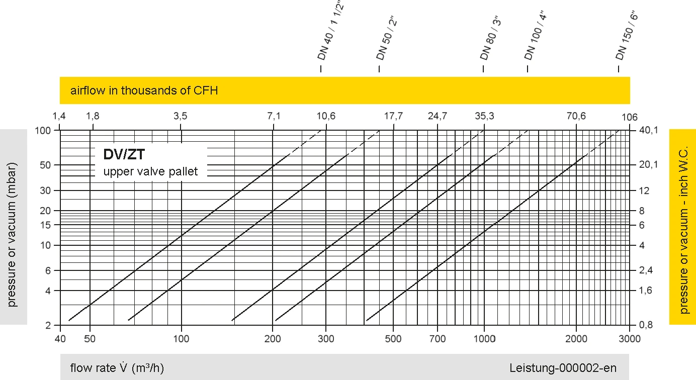
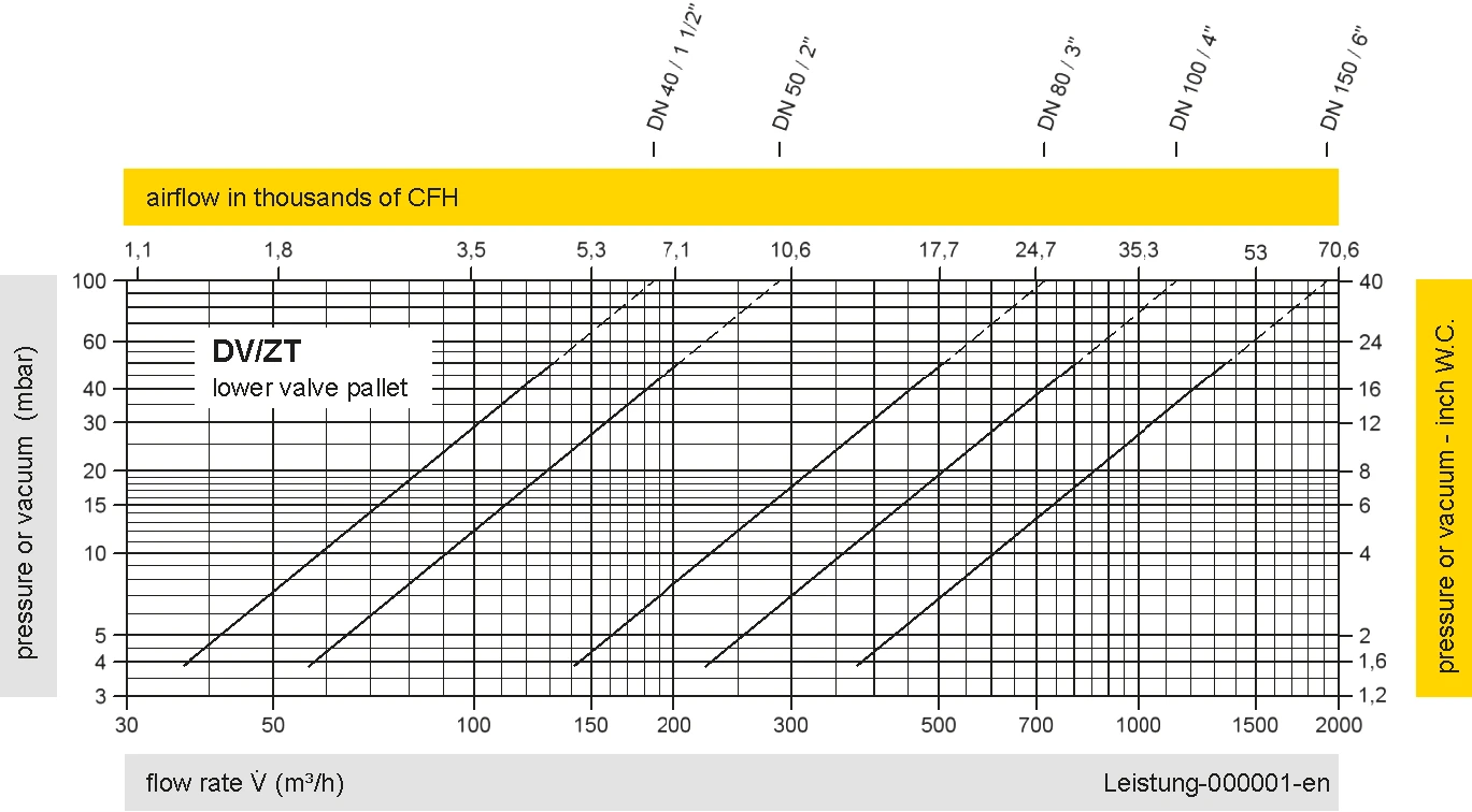
Los diagramas de flujo volumétrico han sido determinados con un banco de pruebas de caudal calibrado y certifi - cado por TÜV. El flujo volumétrico V. en [m³/h] y el CFH se refi eren a las condiciones estándar de referencia de aire según ISO 6358 (20°C, 1bar). La conversión a otras densidades y temperaturas están referidas en el Vol. 1: “Fundamentos Técnicos”.
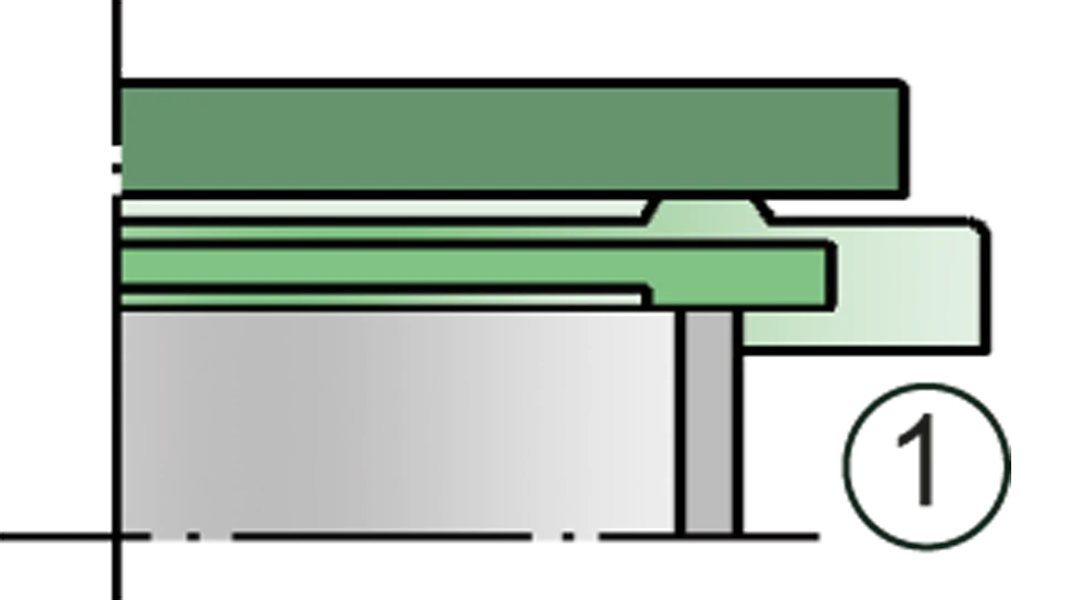
Detail X
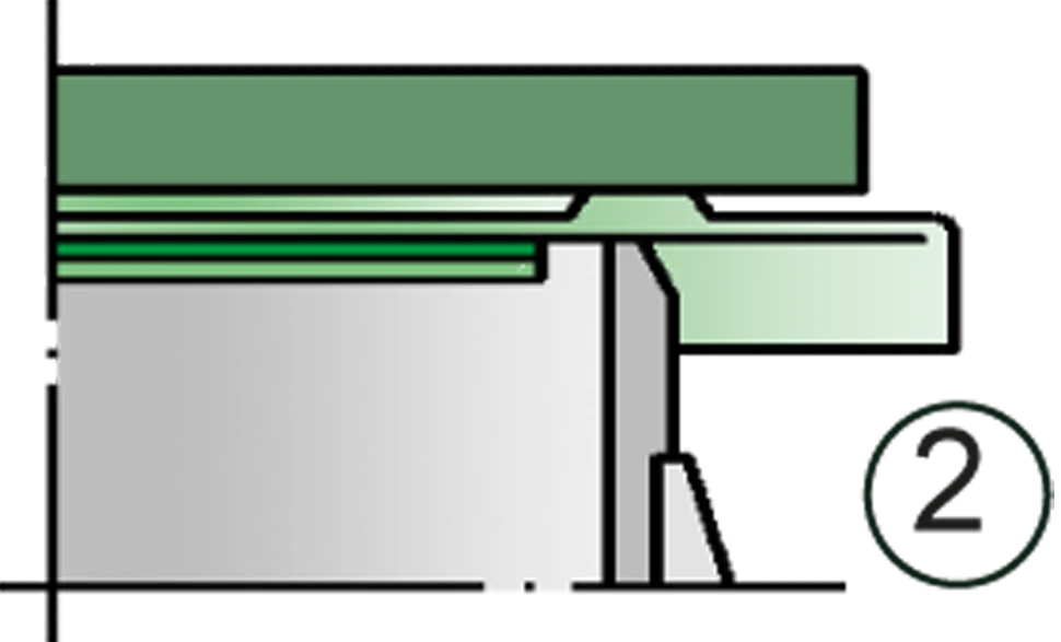
Detail X

Tank connection; Other arrangement of the tank connection upon request.