NB/AP
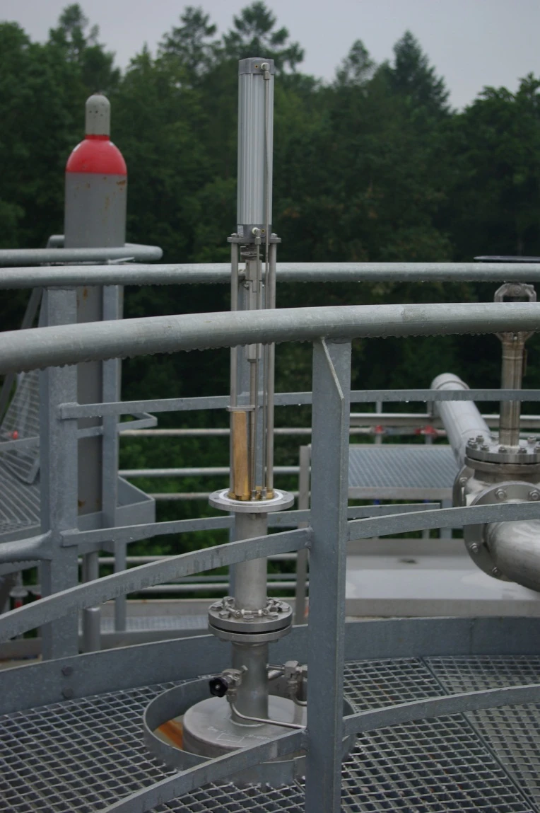
In-Tank Valve with pneumatic actuator
Features
Para tanques criogénicos
Apto para uso en tanques criogénicos
Concepto a prueba de fallos
En caso de una caída de energía, el pistón de la válvula sella la línea de salida por su propio peso
API 625
Estos dispositivos cumplen con los requisitos de la API 625
Estanqueidad
Buena estanqueidad de la válvula
Cable de emergencia en caso de avería
Un cable de emergencia abre la válvula si el cable principal está dañado
Cilindro neumático
Los dispositivos se mantienen abiertos mediante un cilindro neumático
Function and Description
Quick-Release Bottom Drain Valves for Cryogenic Storage Tanks
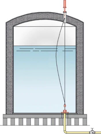
PROTEGO® NB/AP In-Tank Valves are used in storage tanks for cryogenic liquids in order to seal off discharge lines in the event of an accident or emergency (pipe bursting). These devices meet the Requirements of API 625.
Tightness by a Lapped Metallic Valve Pallet and Relief Valve Cone
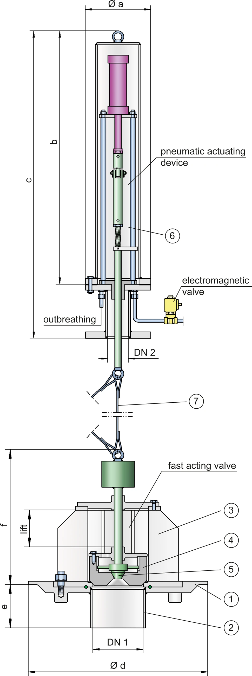
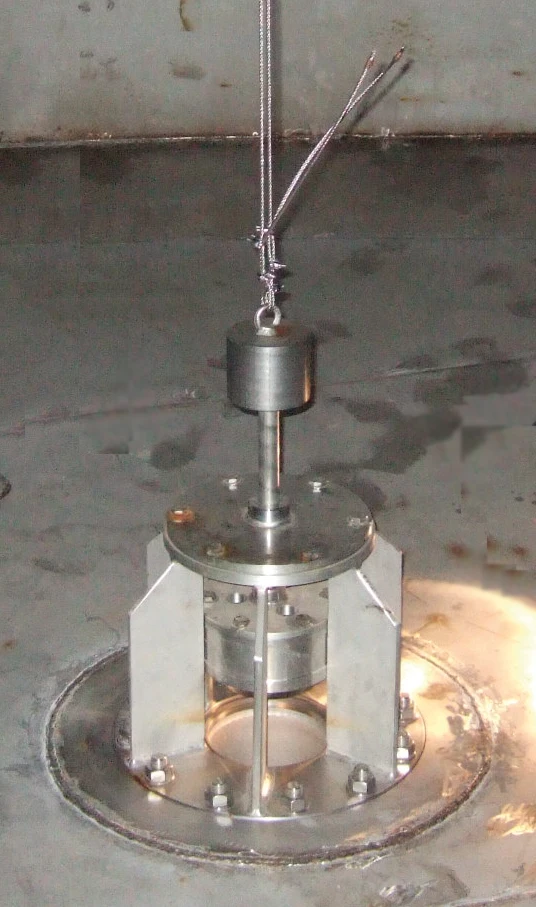
The device consists of the bottom plate (1) which has to be welded onto the vessel bottom; a nozzle (2) which has to be welded to the discharge line; the flanged fast-acting valve (3) with valve piston (4) and release valve cone (5); and the complete pneumatic actuating device (6) which is mounted onto the roof of the tank. The required tightness is ensured by a lapped metallic valve pallet and relief valve cone. The quick-release valve (3) and the actuating system (6) are connected by an actuator cable (7). An additional emergency cable enables the quick-release valve to be opened if the main actuator rope is damaged.
Fail-Safe-Concept
During normal operation, a pneumatic cylinder holds the valves in the open position. The pneumatic cylinder is actuated by a control line to lift the valve piston. The bottom valve is only closed in an emergency. In the event of an energy drop, the valve piston, due to its own weight, falls onto the valve seat which closes the bottom valve.(Fail Safe Concept).
Customized Solutions for Specific Plant Requirements
The valve design is independent of the nominal size. The nominal size DN 1 is determined by the nominal size of discharge line. Material selection depends on the substance and the operating temperature.
Product Data
Dimensiones
| DN 1 | DN 2 | a | b | c | d | e | f | Hub |
| 150 / 6" | 80 / 3" | 200 / 7.87 | 1130 / 44.49 | 1430 / 56.30 | 550 / 21.65 | 175 / 6.89 | 465 / 18.31 | 160 / 6.30 |
| 200 / 8" | 80 / 3" | 200 / 7.87 | 1130 / 44.49 | 1430 / 56.30 | 600 / 23.62 | 175 / 6.89 | 470 / 18.50 | 160 / 6.30 |
| 250 / 10“ | 80 / 3" | 200 / 7.87 | 1130 / 44.49 | 1430 / 56.30 | 740 / 29.13 | 175 / 6.89 | 485 / 19.09 | 160 / 6.30 |
Dimensiones en mm / pulgadas
Material of fast action bottom drain valve
| Bottom plate with nozzle | * |
| Valve housing with valve cone | Stainless Steel |
| Gasket | * |
| Actuator rope | Stainless Steel |
* upon request
Material
| Housing | Stainless Steel |
| Actuator spindle | Stainless Steel |
| Guide bushing | Copper |
| Gasket | PTFE |
| Protective cap | Stainless Steel |
| Pneumatic cylinder | Aluminium |
Tipo de bridas de conexión
| EN 1092-1, Form B, PN 40 or upon request |