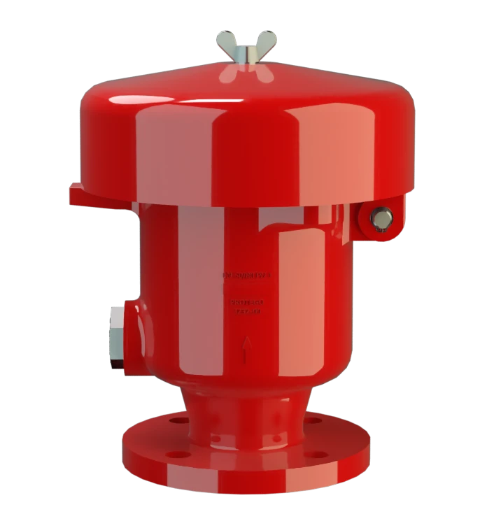
P/EL
Pressure Relief Valve
Features
Tecnología del 10%
para un aumento mínimo de presión hasta alcanzar la apertura completa
Extrema estanqueidad
Lo que se traduce en las menores pérdidas posibles de producto y en una reducción de la contaminación ambiental
Mantenimiento óptimo de la presión
Presión de tarado próxima a la presión de apertura para un mantenimiento óptimo de la presión en el sistema
Flujo volumétrico
Flujo de caudal optimizado
Plato de válvula guiado
El plato de válvula va guiado dentro del cuerpo para protegerlo frente a condiciones meteorológicas adversas
Se usa en zonas con riesgo de explosión
Puede utilizarse en zonas con riesgo de explosión
Drenaje de condensados
Drenaje de condensados automático
Function and Description
Protection Against Overpressure
The P/EL Type PROTEGO® valve is a highly developed pressure relief valve. It is primarily used as a device for relieving pressure in tanks, containers and process engineering equipment. The valve protect against unallowable overpressure and prevents the unacceptable loss of product vapors close to the set pressure.
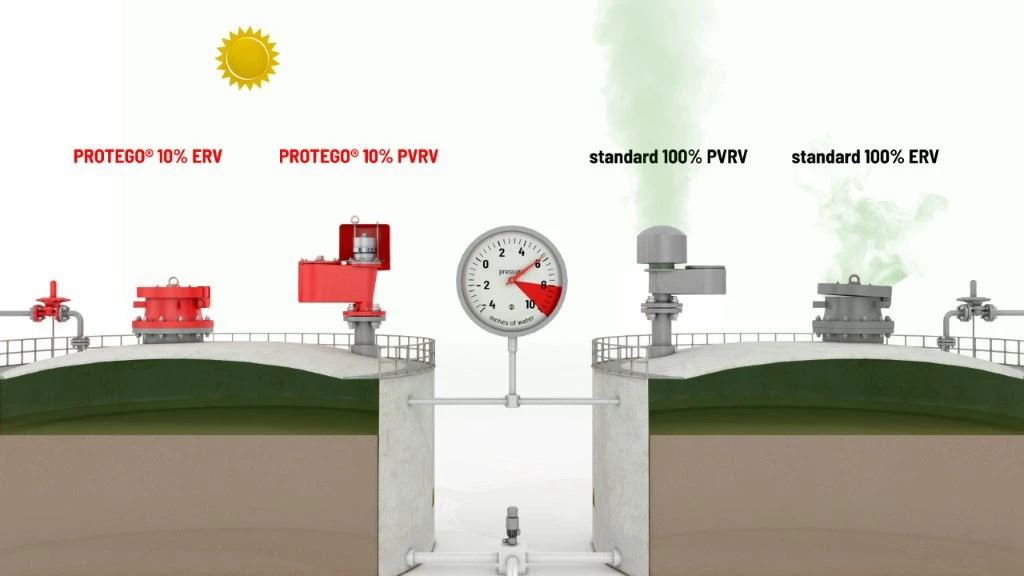
10% Technology
The device will start to open as soon as the set pressure is reached and only requires 10% overpressure to full lift. Continuous investments into research and development have allowed PROTEGO® to develop a low pressure valve which has the same opening characteristic as a high pressure safety relief valve. This “Full Lift Type” technology allows the valve to be set just 10% below the maximum allowable working pressure of the tank and still safely vent the required mass flow.
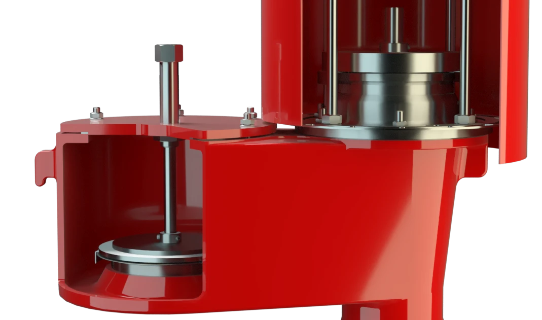
Highly Developed Manufacturing Technology
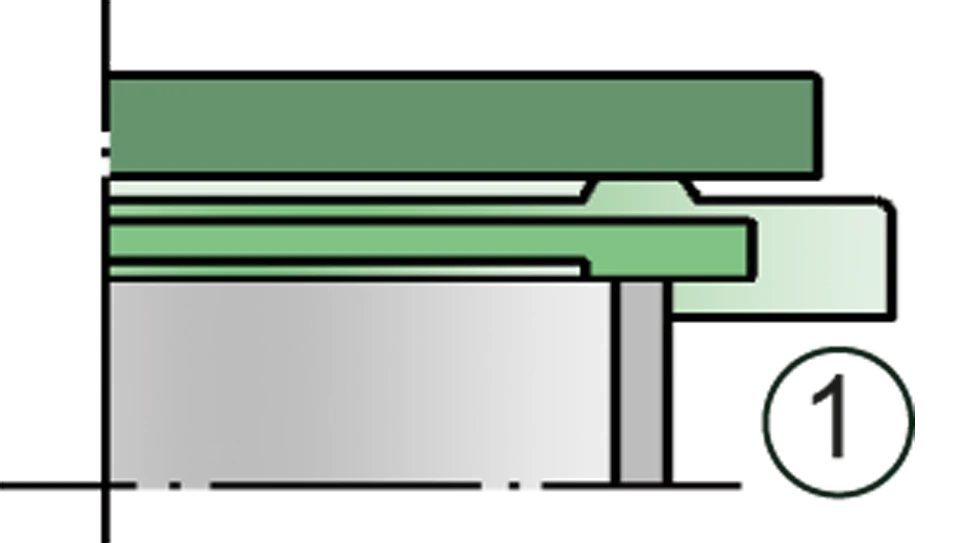
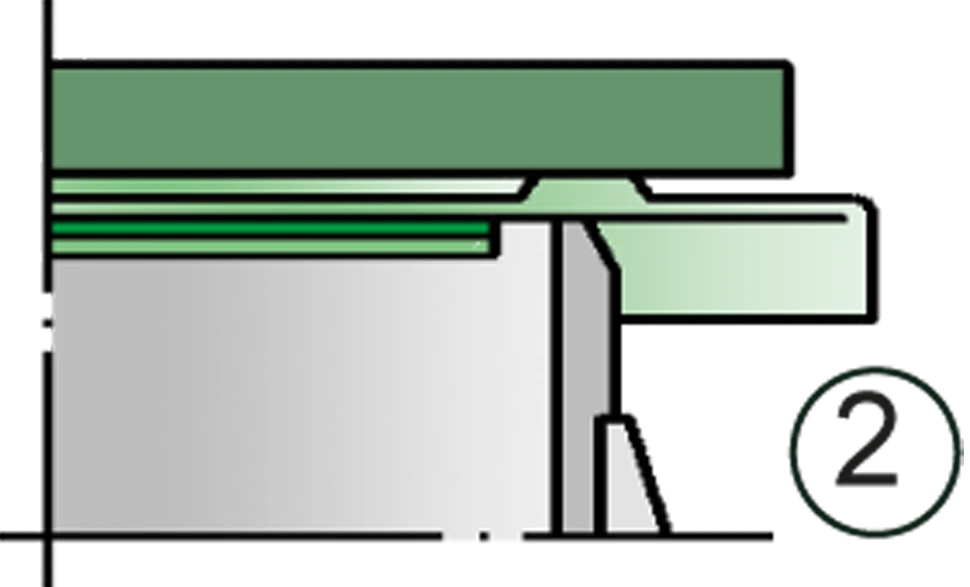
Due to our highly developed manufacturing technology the tank pressure is maintained up to set pressure, with a tightness that is far superior to the conventional standard. This feature is achieved by valve seats made of high quality stainless steel and with precisely lapped valve pallets (1) or with an air cushion seal (2) in conjunction with high quality FEP diaphragm. The valve pallets are also available with a PTFE seal to prevent the valve pallets from sticking when sticky products are used, and they enable the use of corrosive media. After the excess pressure is discharged, the valve reseats and provides a tight seal.
The optimized fluid dynamic design of the valve body and valve pallet is a result of many years of research, resulting in stable operation of the valve pallet, optimized performance, and reduced product losses.
Product Data
Dimensiones
To select the nominal size (DN), use the flow capacity chart on the following page
| DN | 50 / 2" | 50 / 2" | 80 / 3" | 80 / 3" |
| Set pressure | ≤ +80 mbar | > +80 mbar | ≤ +80 mbar | > +80 mbar |
| Set pressure | ≤ +32.1 inch W.C. | > +32.1 inch W.C. | ≤ +32.1 inch W.C. | > +32.1 inch W.C. |
| a | 218 / 8.58 | 218 / 8.58 | 218 / 8.58 | 218 / 8.58 |
| b | 287 / 11.30 | 452 / 17.80 | 289 / 11.38 | 454 / 17.87 |
Dimensiones en mm / pulgadas
Dimensions for pressure valves with heating jacket upon request
Selección de materiales para la vivienda
| Design | B | C |
| Housing | Steel | Stainless Steel |
| Heating jacket (P / EL-H-...) | Steel | Stainless Steel |
| Valve seat | Stainless Steel | Stainless Steel |
| Weather hood | Steel | Stainless Steel |
| Protective mesh screen | Stainless Steel | Stainless Steel |
Special materials upon request
Selección de materiales para la válvula de presión
| Design | A | B | C | D |
| Pressure range [mbar] [inch W.C.] | +3,5 up to +5,0 +1.4 up to +2.0 | >+5,0 up to +14 >+1.4 up to 5.6 | >+14 up to +210 >+5.6 up to +84 | >+14 up to +210 >+5.6 up to +84 |
| Valve pallet | Aluminium | Stainless Steel | Stainless Steel | Stainless Steel |
| Sealing | FEP | FEP | Metal to Metal | PTFE |
Special materials(Aluminium-coated, Titanium, Hastelloy) and higher pressure Settings upon request
Tipo de bridas de conexión
| EN 1092-1; Form B1 |
| ASME B16.5 CL 150 R.F. |
other types upon request
Diagrama de flujo volumétrico
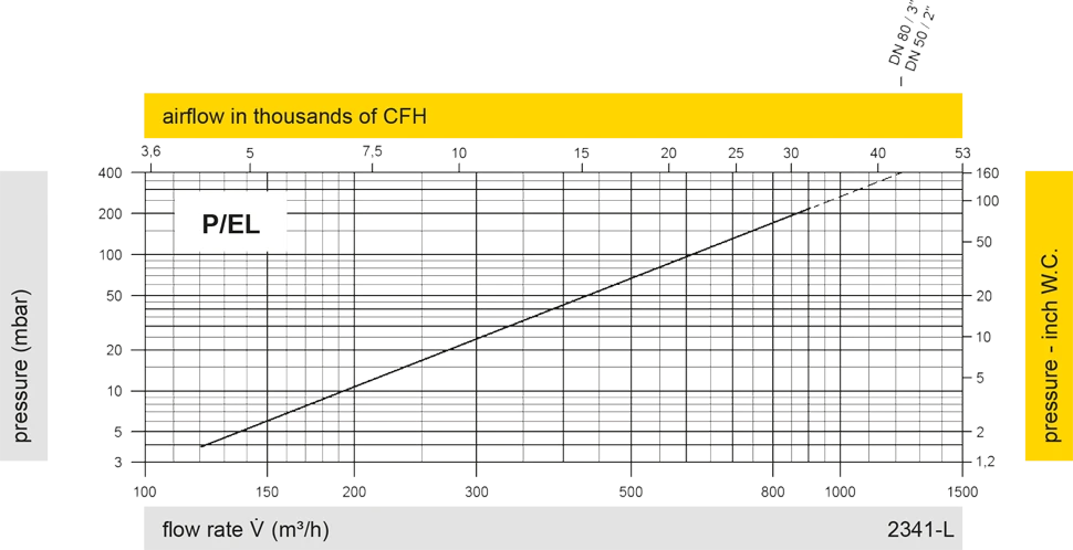
Los diagramas de flujo volumétrico han sido determinados con un banco de pruebas de caudal calibrado y certifi - cado por TÜV. El flujo volumétrico V. en [m³/h] y el CFH se refi eren a las condiciones estándar de referencia de aire según ISO 6358 (20°C, 1bar). La conversión a otras densidades y temperaturas están referidas en el Vol. 1: “Fundamentos Técnicos”.
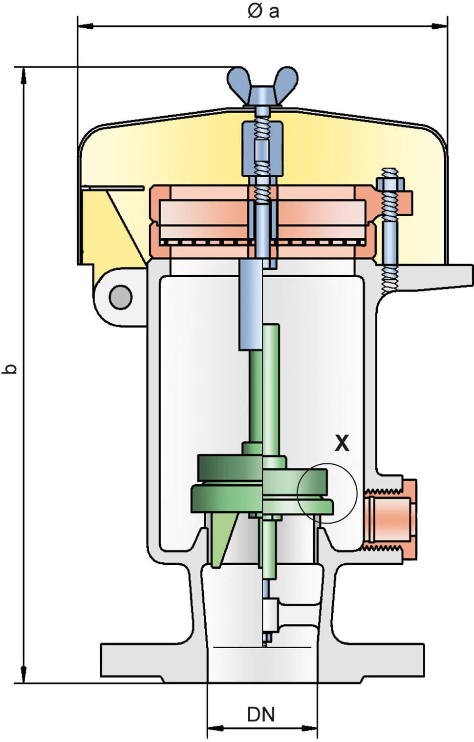
Detail X
Detail X