BE/HR-D
Pressure Relief Valve deflagration- and endurance burning-proof
Features
Plato de válvula guiado
El plato de válvula va guiado dentro del cuerpo para protegerlo frente a condiciones meteorológicas adversas
Sistema de protección conforme a ATEX
Puede utilizarse como sistema de protección en zonas con atmósferas potencialmente explosivas según ATEX
Extrema estanqueidad
Lo que se traduce en las menores pérdidas posibles de producto y en una reducción de la contaminación ambiental
Seguridad contracombustión prolongada
Protección contra deflagraciones atmosféricas y combustión prolongada
Apagallamas integrado
La unidad apagallamas PROTEGO® integrada ahorra espacio y peso y reduce costes
Flujo volumétrico
Flujo de caudal optimizado
Function and Description
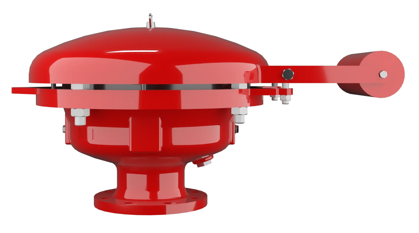
Pressure Relief Valve with Integrated PROTEGO® Flame Arrester
The Deflagration-Proof and Endurance-Burning-Proof BE/HR-D Type PROTEGO® valve is a highly developed pressure relief valve with an integrated Flame Arrester Unit. It is primarily used as a device for flame transmission proof outbreathing on tanks, containers and process engineering apparatus. The valve offers reliable protection against excess pressure and prevents product losses almost up to the set pressure; it also protects against atmospheric deflagration as well as endurance burning if stabilized burning occurs. The PROTEGO® Flame Arrester Unit is designed to achieve minimum pressure drop with maximum safety. The BE/HR-D valve is available for substances of explosion group IIA (NEC group D MESG > 0.9 mm).
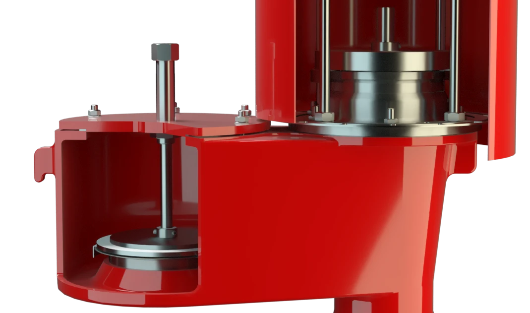
Advanced Manufacturing Technology
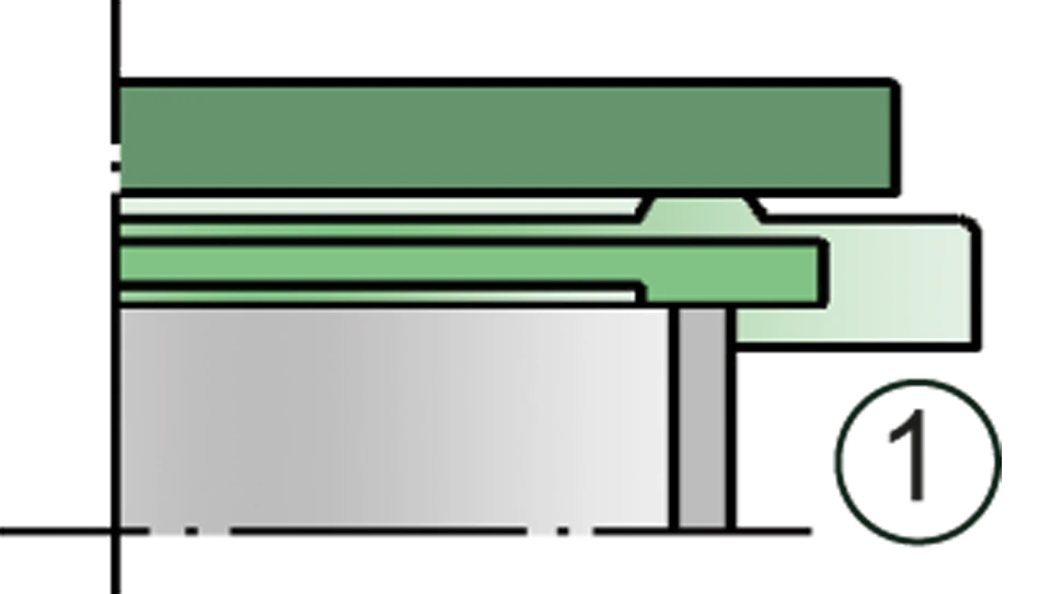
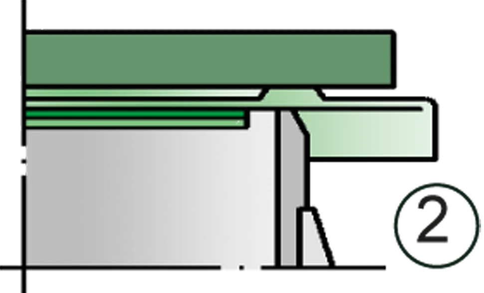
When the set pressure is reached, the valve starts to open and reaches full lift within 40% overpressure. The tank pressure is maintained up to the set pressure with a tightness that is far superior to the conventional standard due to our state of the art manufacturing technology. This feature is ensured by the valve seats made of high quality stainless steel and with individually lapped valve pallets (1) or with an air cushion seal (2) in conjunction with high quality FEP diaphragm. After the excess pressure is discharged, the valve reseats and provides a tight seal.

Many Individual Certifications
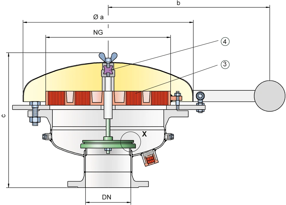
If the set pressure is exceeded, explosive gas/product-vapour air mixtures are released to the atmosphere. If this mixture ignites, the integrated PROTEGO® Flame Arrester Unit (3) prevents flame transmission into the tank. If additional mixture continues to flow and stabilized burning occurs, the integrated Flame Arrester Unit prevents flashback as a result from endurance burning. The valve is protected and also fulfils its function under this severe service conditions. The spring loaded weather hood opens as soon as the fusible element (4) melts. The valve can be used up to an operating temperature of +60°C / 140°F and meets the requirements of European Tank Design Standard EN 14015 – Appendix L and ISO 28300 (API 2000). EU conformity according to the currently valid ATEX directive. Approvals according to other national/international regulations on request.
Product Data
Dimensiones
To select the nominal size (DN), please use the flow capacity chart on the following page
| DN | 150 / 6" | 200 / 8" | |
| NG | 400 / 16" | 400 / 16" | |
| a | 600 / 23.62 | 600 / 23.62 | |
| b | 545 / 21.46 | 545 / 21.46 | |
| c | 485 / 19.09 | 485 / 19.09 | NG = Nominal size |
Dimensiones en mm / pulgadas
Selección del grupo de explosión
| MESG | Expl. Gr. (IEC / CEN) | Gas Group (NEC) |
| > 0,90 mm | IIA | D |
Special approvals upon request
Selección de materiales para la vivienda
| Design | A | B |
| Housing | Steel | Stainless Steel |
| Valve seat | Stainless Steel | Stainless Steel |
| Weather Hood | Steel | Stainless Steel |
| Flame arrester unit | A | B |
Special materials upon request
Combinación de materiales para la unidad apagallamas
| Design | A | B |
| FLAMEFILTER® cage | Steel | Stainless Steel |
| FLAMEFILTER® | Stainless Steel | Stainless Steel |
Special materials upon request
Material selection for valve pallet
| Design | A | B | C |
| Pressure range [mbar] [inch W.C.] | +2.0 up to +3.5 +0.8 up to +1.4 | >+3.5 up to +14 >+1.4 up to +5.6 | >+14 up to +35 >+5.6 up to +14 |
| Valve pallet | Aluminium | Stainless Steel | Stainless Steel |
| Sealing | FEP | FEP | Metal to Metal |
Special materials and higher pressure settings upon request
Tipo de bridas de conexión
| EN 1092-1; Form B1 |
| ASME B16.5 CL 150 R.F. |
other types upon request
Diagrama de flujo volumétrico
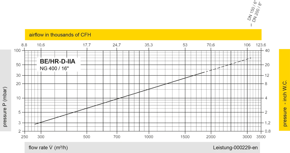
Los diagramas de flujo volumétrico han sido determinados con un banco de pruebas de caudal calibrado y certifi - cado por TÜV. El flujo volumétrico V. en [m³/h] y el CFH se refi eren a las condiciones estándar de referencia de aire según ISO 6358 (20°C, 1bar). La conversión a otras densidades y temperaturas están referidas en el Vol. 1: “Fundamentos Técnicos”.
Detail X
Detail X