ZM-R
Blanketing Valve low pressure reducing valve
Features
Gran superficie del diafragma
Para aumentar la fuerza de cierre
Acero inoxidable o hastelloy
Todas las piezas relevantes para el funcionamiento y en contacto con el producto están fabricadas en acero inoxidable o Hastelloy
Ajuste sencillo de la presión de tarado
(dentro del rango del muelle)
Cualquier posición de instalación
(teniendo en cuenta la presión de tarado)
Fuente de alimentación externa
No se necesita suministro de energía externo
Alta capacidad volumétrica
Reduce costes mediante el uso de válvulas más pequeñas
Plato de válvula guiado
El plato de válvula va guiado dentro del cuerpo para protegerlo frente a condiciones meteorológicas adversas
Precisión
Alta precisión
Se usa en zonas con riesgo de explosión
Puede utilizarse en zonas con riesgo de explosión
Diseño de cuerpo robusto
(PN 10 & PN 16)
Function and Description
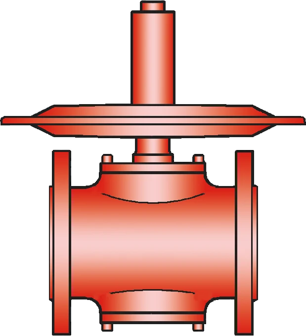
Highly Developed Low-Pressure Reducing Valve
The Blanketing Valve Type ZM-R is a highly developed low pressure reducing valve. This valve is typically used to inert or blanket tanks, vessels, or other process systems with Nitrogen or other blanketing gases by controlling the tank pressure to ist desired value. High Nitrogen or blanketing gas supply pressures up to 16 bar / 232 psi are safely reduced down to only a few mbar / inch W.C..
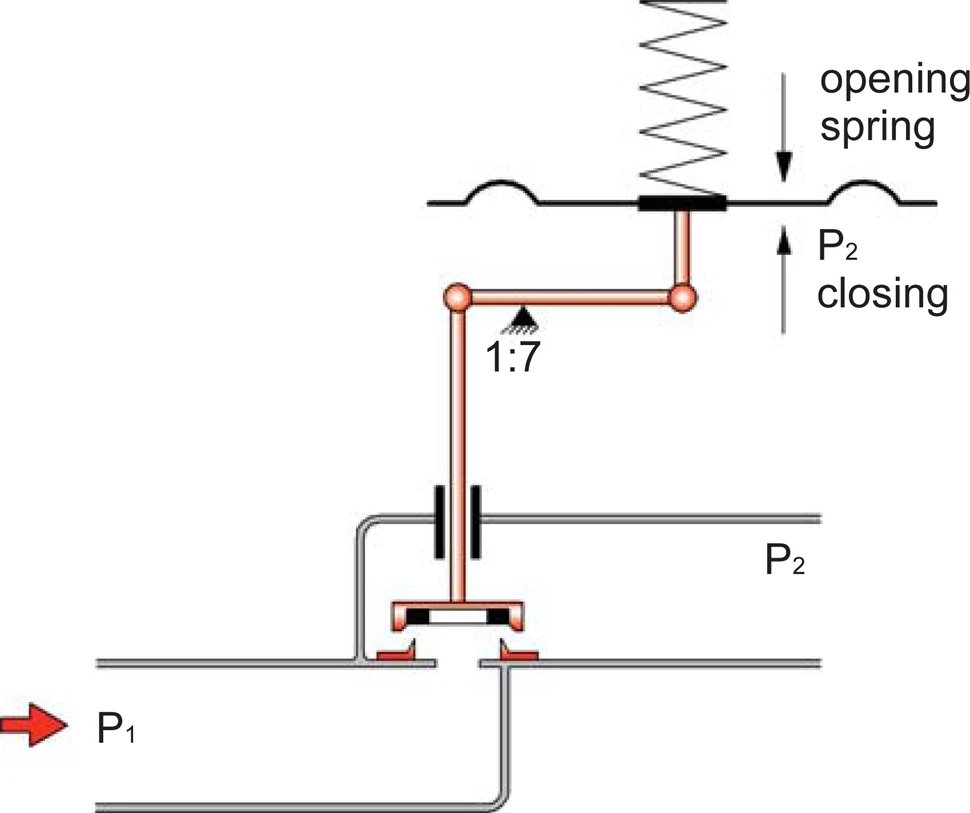
Membrane-Controlled and Spring-Loaded Proportional Regulator
The ZM-R low pressure reducing valve is a direct acting, one stage pressure control device. It is designed as a diaphragm controlled, spring-loaded proportional acting valve. The valve controls the tank pressure by increasing flow as the tank pressure drops. This means that the mass flow through the valve depends on the pressure differential of the set pressure to the actual tank pressure. When the actual tank pressure reaches the set pressure, the control unit closes, and there is no flow.
For Precise Pressure Control
At the control diaphragm, (which can be made from PTFE or Viton), the tank pressure (P2) is balanced with the adjustment spring and the supply pressure (P1). In a depressurized tank, the adjustment spring holds the valve pallet in the fully open position. As the tank pressure increases, the valve pallet moves toward the seat, and the mass flow is reduced. When the desired tank pressure is reached, the valve will close.
Precise Pressure Control up to -200 mbar
If the tank pressure decreases, the valve will open. If the system is operated in a vacuum mode, vacuum pressures down to -200 mbar /-80 inch W.C. (relative pressure) can be achieved.
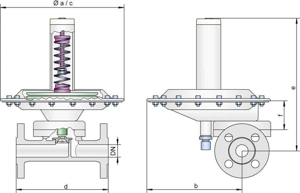
Product Data
Dimensiones
To select the nominal size (DN), please use the flow capacity charts on the following pages
| DN | 15 / ½" | 25 / 1'' | 50 / 2'' | 100 / 4'' | 15 / ½" | 25 / 1'' | 50 / 2'' | 100 / 4'' | |
| a | 214 | 214 | – | – | 8.43 | 8.43 | – | – | |
| b | 168 | 168 | – | – | 6.61 | 6.61 | – | – | |
| c* | – | – | 214 / 360 | 360 / 600 | – | – | 8.43 / 14.17 | 14.17 / 23.62 | |
| d | DIN | 150 | 160 | 150 | 250 / 250 | 5.91 | 6.3 | 5.91 | 9.84 / 9.84 |
| ANSI | 180 | 160 | 150 | 250 / 250 | 7.09 | 6.3 | 5.91 | 9.84 / 9.84 | |
| e | 214 | 214 | 230 | 275 / 310 | 8.43 | 8.43 | 9.06 | 10.83 / 12.2 | |
| f | 87 | 87 | 103 | 148 / 155 | 3.43 | 3.43 | 4.06 | 5.83 / 6.10 |
Dimensiones en mm / pulgadas
*depends upon size of diaphragm
Dimensiones
Selection of valve seat depending on flow rate
| Size | Seat in mm / inches | Kvs | Number |
| 25 / 1'' | 2,0 / 0.08 | 0,15 | 20 |
| 4,5 / 0.18 | 0,60 | 45 | |
| 7,5 / 0.30 | 1,20 | 75 | |
| 10,0 / 0.39 | 1,70 | 100 | |
| 14,0 / 0.55 | 2,40 | 140 | |
| 50 / 2'' | 14,0 / 0.55 | 2,80 | 140 |
| 18,0 / 0.71 | 6,80 | 180 | |
| 26,0 / 1.02 | 14,50 | 260 | |
| 100 / 4'' | 42,0 / 1.65 | 33,50 | 420 |
| 55,0 / 2.17 | 68,00 | 550 |
*1 Kvs = 0.86 Cv; 1 Cv = 1.17 Kvs
Selección de materiales para la vivienda
| Design | S | H | |
| Housing | Stainless Steel | Hastelloy | |
| Valve seat | Stainless Steel | Hastelloy | |
| Valve pallet | Stainless Steel | Hastelloy | |
| Valve seat sealing | FFKM | FFKM | |
| Gasket | PTFE | PTFE | |
| Diaphragm P | PTFE | PTFE | Marking P |
| Alternative: Diaphragm V | Viton | - | Marking V |
Optional: Inner part of housing electropolished. Special materials upon request
Tipo de conexión
| FD | DIN 2501, PN 16 | DIN |
| FA | ASME B16.5 CL 150 R.F. | ASME |
| G | Thread | G or NPT |
other types upon request
Flow rates for P2 pressure range (Europe - metric units)
ZM-R 15 / ZM-R 25: flow rate (air, 0°C) at ∆P = P1 - P2 and valve full open
| P 1 (bar) | 0,15 | 0,25 | 0,40 | 0,65 | 1,00 | 1,50 | 2,50 | 4,00 | 6,00 | 10,00 | Sitz-Ø |
| P 2 (mbar) | [Nm³ / h] | [Nm³ / h] | [Nm³ / h] | [Nm³ / h] | [Nm³ / h] | [Nm³ / h] | [Nm³ / h] | [Nm³ / h] | [Nm³ / h] | [Nm³ / h] | [mm] |
| 10 | 6,2 12,4 17,5 24,8 | 8,1 16,2 23,0 32,5 | 10,3 20,7 29,3 41,4 | 13,2 26,5 37,6 53,1 | 16,5 33,0 46,7 66,0 | 20,6 41,2 58,4 82,4 | 28,8 57,6 81,6 115,2 | 41,1 82,2 116,5 164,5 | 57,5 115,0 163,0 230,1 | 90,3 180,7 256,0 361,4 | Ø4,5 Ø7,5 Ø10,0 Ø14,0 |
| 20 | 6,0 12,0 17,0 24,0 | 7,9 15,9 22,6 31,9 | 10,2 20,5 29,1 41,1 | 13,2 26,4 37,5 52,9 | 16,5 33,0 46,7 66,0 | 20,6 41,2 58,4 82,4 | 28,8 57,6 81,6 115,2 | 41,1 82,2 116,5 164,5 | 57,5 115,0 163,0 230,1 | 90,3 180,7 256,0 361,4 | Ø4,5 Ø7,5 Ø10,0 Ø14,0 |
| 100 | 3,8 7,7 10,9 15,4 | 6,7 13,4 18,9 26,8 | 9,4 18,9 26,8 37,9 | 12,8 25,6 36,3 51,3 | 16,4 32,8 46,5 65,6 | 20,6 41,2 58,4 82,4 | 28,8 57,6 81,6 115,2 | 41,1 82,2 116,5 164,5 | 57,5 115,0 163,0 230,1 | 90,3 180,7 256,0 361,4 | Ø4,5 Ø7,5 Ø10,0 Ø14,0 |
| 200 | - - - - | 4,0 8,0 11,4 16,1 | 8,00 16,1 22,9 32,3 | 12,1 24,2 34,3 48,4 | 16,1 32,3 45,8 64,6 | 20,6 41,2 58,4 82,4 | 28,8 57,6 81,6 115,2 | 41,1 82,2 116,5 164,5 | 57,5 115,0 163,0 230,1 | 90,3 180,7 256,0 361,4 | Ø4,5 Ø7,5 Ø10,0 Ø14,0 |
| 500 | - - - - | - - - - | - - - - | 7,8 15,6 22,1 31,2 | 14,2 28,5 40,4 57,0 | 20,1 40,3 57,1 80,7 | 28,8 57,6 81,6 115,2 | 41,1 82,2 116,5 164,5 | 57,5 115,0 163,0 230,1 | 90,3 180,7 256,0 361,4 | Ø4,5 Ø7,5 Ø10,0 Ø14,0 |
Flow rates for P2 pressure range (Europe - metric units)
ZM-R 50: flow rate (air, 0°C) at ∆P = P1 - P2 and valve full open
| P 1 (bar) | 0,15 | 0,25 | 0,40 | 0,65 | 1,00 | 1,50 | 2,50 | 4,00 | 6,00 | 10,00 | Sitz-Ø |
| P 2 (bar) | [Nm³ / h] | [Nm³ / h] | [Nm³ / h] | [Nm³ / h] | [Nm³ / h] | [Nm³ / h] | [Nm³ / h] | [Nm³ / h] | [Nm³ / h] | [Nm³ / h] | [mm] |
| 10 | 28,9 70,3 150,0 | 37,9 92,1 196,5 | 48,3 117,4 250,4 | 61,9 150,4 320,8 | 77,0 187,1 399,1 | 96,2 233,6 498,3 | 134,5 326,6 696,5 | 191,9 466,1 994,0 | 268,5 652,1 1390 | 421,6 1024 2183 | Ø14,0 Ø18,0 Ø26,0 |
| 20 | 28,0 68,1 145,3 | 37,3 90,6 193,3 | 47,9 116,5 248,4 | 61,7 150,0 319,9 | 77,0 187,1 399,0 | 96,2 233,6 498,3 | 134,5 326,6 696,5 | 191,9 466,1 994,0 | 268,5 652,1 1390 | 421,6 1024 2183 | Ø14,0 Ø18,0 Ø26,0 |
| 100 | 18,0 43,8 93,5 | 31,2 75,9 162,0 | 44,2 107,4 229,1 | 59,9 145,5 310,2 | 76,6 186,1 396,9 | 96,2 233,6 498,3 | 134,5 326,6 696,5 | 191,9 466,1 994,0 | 268,5 652,1 1390 | 421,6 1024 2183 | Ø14,0 Ø18,0 Ø26,0 |
| 200 | - - - | 18,8 45,8 97,6 | 37,7 91,6 195,3 | 56,5 137,4 293,0 | 75,4 183,2 390,6 | 96,2 233,6 498,3 | 134,5 326,6 696,5 | 191,9 466,1 994,0 | 268,5 652,1 1390 | 421,6 1024 2183 | Ø14,0 Ø18,0 Ø26,0 |
| 500 | - - - | - - - | - - - | 36,4 88,6 188,9 | 66,6 161,7 344,9 | 94,1 228,7 487,8 | 134,5 326,6 696,5 | 191,9 466,1 994,0 | 268,5 652,1 1390 | 421,6 1024 2183 | Ø14,0 Ø18,0 Ø26,0 |
Flow rates for P2 pressure range (Europe - metric units)
ZM-R 100: flow rate (air, 0°C) at ∆P = P1 - P2 and valve full open
| P 1 (bar) | 0,15 | 0,25 | 0,40 | 0,65 | 1,00 | 1,50 | 2,50 | 4,00 | 6,00 | 10,00 | Sitz-Ø |
| P 2 (bar) | [Nm³ / h] | [Nm³ / h] | [Nm³ / h] | [Nm³ / h] | [Nm³ / h] | [Nm³ / h] | [Nm³ / h] | [Nm³ / h] | [Nm³ / h] | [Nm³ / h] | [mm] |
| 10 | 346 703 | 453 921 | 587 1174 | 741 1504 | 922 1871 | 1151 2336 | 1609 3266 | 2296 4661 | 3212 6512 | 5045 10241 | Ø42,0 Ø55,0 |
| 20 | 335 681 | 446 906 | 574 1165 | 739 1500 | 921 1871 | 1151 2336 | 1609 3266 | 2296 4661 | 3212 6512 | 5045 10241 | Ø42,0 Ø55,0 |
| 100 | 216 438 | 374 759 | 529 1074 | 716 1455 | 917 1861 | 1151 2336 | 1609 3266 | 2296 4661 | 3212 6512 | 5045 10241 | Ø42,0 Ø55,0 |
| 200 | - - | 225 458 | 451 916 | 676 1374 | 902 1832 | 1151 2336 | 1609 3266 | 2296 4661 | 3212 6512 | 5045 10241 | Ø42,0 Ø55,0 |
| 500 | - - | - - | - - | 436 886 | 796 1617 | 1127 2287 | 1609 3266 | 2296 4661 | 3212 6512 | 5045 10241 | Ø42,0 Ø55,0 |
Flow rates for P2 vacuum range (Type ZM-R/N) upon request