Features
Venting and Breathing of Floating Roof Tanks
The Device Is Used for Automatic Venting and Breathing of Floating Roof Tanks
Low Position of the Floating Roof
In the Low Position of the Floating Roof, the Valve Opens Automatically to Prevent Vacuum or Overpressure
Different Heights
Due to Different Heights of the Floating Roof's Low Position for Operational and Assembly Settings, Specific Dimensions Must Be Provided
Conversion
During the Conversion of the Floating Roof's Support Legs From Operational to Maintenance Position, the Plunger Must Be Extended
Adjustment Through an Adjustment Option
Adjustment Is Achieved Through an Adjustment Option Using a Locking Pin Secured With a Cotter Pin
Not Flame Transmission Proof
The Valve Is Not Flame Transmission Proof
Flameproof Venting of the Tank
Depending on Requirements, Two or Four Deflagration- and Endurance-Burning-Proof Atmospheric Flame Arresters Can Be Installed to Ensure Flameproof Venting of the Tank
Function and Description
Automatic Venting Valves for Floating Roof Tanks
PROTEGO® Lift-Actuated Vent Valves Type AL-DK-D provide automatic venting of
floating roof
Toit flottant
A floating roof is the roof of a tank that is fitted with floating chambers (pontoons) and lies on top of the liquid.
tanks when the floating roof is lowered onto its supports and the tank is either drained or refilled. When the floating roof is in its lowest position, the valve is forced to open through
lift
Course
Lift is the actual travel of the valve pallet from the main valve out of the closed position.
actuation, which prevents inadmissible
vacuum
Dépression
Vacuum is the pressure in an enclosed space that is lower than the ambient pressure.
during final draining or inadmissible pressure during refilling.
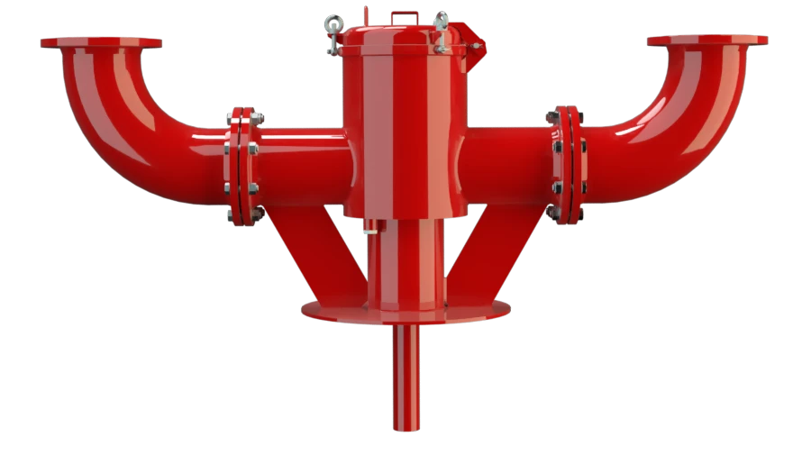
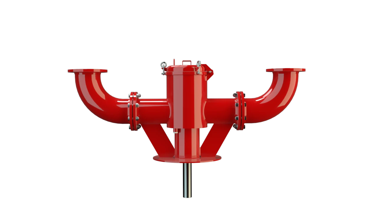
Design of Valves
The PROTEGO® AL-DK-D valve consists of a
housing
Corps
A housing is a solid shell, which surrounds a content, either protecting the content from external influences, or protecting the environment from the content.
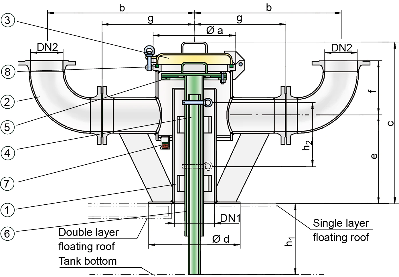
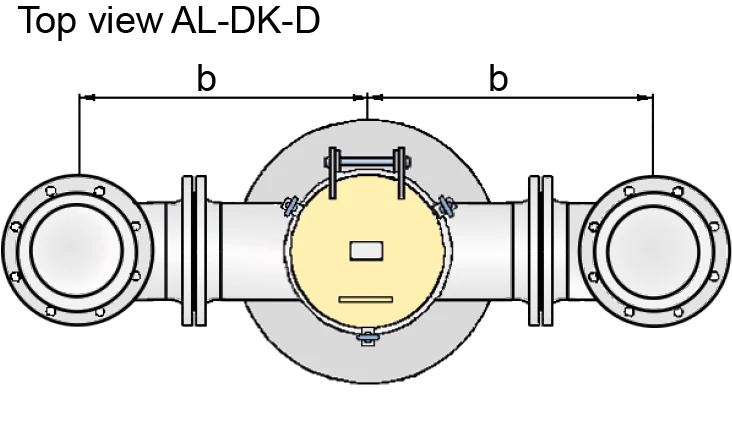
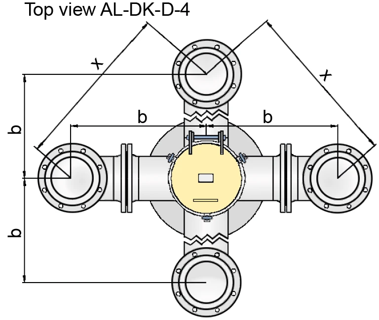
(1) with a sheet metal panel to be welded onto the floating roof or a flange for mounting on a mating flange, two or four flanged connection nozzles (2) for installation of vent caps, cover (3), lift (4) including valve disc (5), lift pipe (6), and the condensate drain valve (7) which can be designed to be flame transmission proof. The condensate drain is sealed by a flat gasket attached to the valve disk (5). The cover (3) is sealed by a
sealing cord
Cordon d'étanchéité
A sealing cord is a synthetic cord with a circular or square profile. It is used to seal off components.
(8).
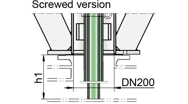
Dimensions for Different Floating Roof Heights
As the lowest position of the floating roof varies for operation and assembly, specify the dimensions h1 and h2:
h1: Distance between the lower edge of the connection of the equipment and the tank bottom at the lowest level of the floating roof in the operating position (operating position with an empty tank).
h2: Distance between the lowest level of the floating roof in the maintenance position and the lowest level of the floating roof in the operating position (operating position with an empty tank).
Conversion of Floating Roof Supports and Extension of the Plunger
If the floating roof supports are changed from operating position to maintenance position, the lift has to be extended as well. This is done with an adjustable locking pin that is secured with a split pin.
The valve is not flame transmission proof.
Based on a hazard analysis with regard to material selection and function, the valves have no potential ignition sources. As a result, they are not subject to the European
Explosion
Explosion
Réaction brusque d’oxydation ou de décomposition entraînant une élévation de température, de pression ou des deux simultanément.
Protection Directive (ATEX) when used in explosive atmospheres.
Combined With Atmospherically Deflagration and Endurance Burning Proof Vent Caps
Lift-actuated vent valves PROTEGO® AL-DK-D can be combined with atmospherically deflagration-proof and
endurance burning
Endurance burning
Stabilized burning for an unlimited time.
-proof vent caps.
Product Data
Dimensions
| AL-DK-D | AL-DK-D-4 | |||
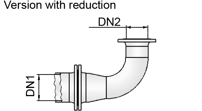
| DN1 | 200 / 8" | 200 / 8" | 200 / 8" | 200 / 8" |
| DN2 | 150 / 6" | 200 / 8" | 150 /6" | 200 / 8" |
| a | 350 / 13.78 | 350 / 13.78 | 350 / 13.78 | 350 / 13.78 |
| b | 905-1580 / 35.63-62.02 | 830-1580 / 32.68-62.02 | 689-1950 / 27.13-76.77 | 689-1950 / 27.13-76.77 |
| c | 870 / 34.25 | 870 / 34.25 | 870 / 34.25 | 870 / 34.25 |
| d | 600 / 23.62 | 600 / 23.62 | 600 / 23.62 | 600 / 23.62 |
| e | 415 / 16.34 | 415 / 16.34 | 415 / 16.34 | 415 / 16.34 |
| f | 370 / 14.57 | 370 / 14.57 | 370 / 14.57 | 370 / 14.57 |
| g | 460 / 18.11 | 460 / 18.11 | 460 / 18.11 | 460 / 18.11 |
| x | 974-1950 / 38.35-76.77 | 974-1950 / 38.35-76.77 | ||
| Weight (kg)* | max. 254 | max. 277 | max. 392 | max. 489 |
Dimensions in mm / inches
* The dimensions and weight vary depending on the type of endurance burning flame arrester.
Material
| Housing | Steel |
| Valve guide | Stainless Steel |
| Gasket | FPM |
Special materials upon request
Flange connection type
| EN 1092-1; Form B1 | andere Anschlüsse auf Anfrage |
| ASME B16.5 CL 150 R.F. |
Other types upon request
Flow Capacity Chart
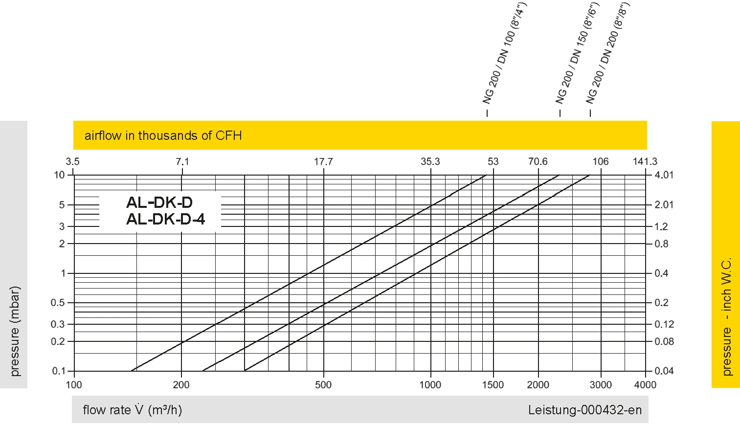
The flow capacity charts have been determined with a calibrated and TÜV certified flow capacity test rig. Volume flow V in (m³/h) and CFH refer to the standard reference conditions of air ISO 6358 (20°C, 1bar). For conversion to other densities and temperatures refer to Sec. 1: “Technical Fundamentals”.
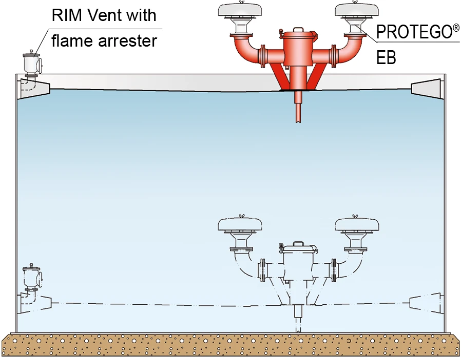
Application Example for PROTEGO® AL-DK-D
Lift-actuated vent valves of type PROTEGO® AL-DK-D can be combined with vent caps type PROTEGO® BE/HR-400 or PROTEGO® EB .


Finding your location…
 PROTEGO®
 Representative
 PARC / Service Partner
No results found