DV/ZW-F
Pressure and Vacuum Relief Valve, In-Line

Features
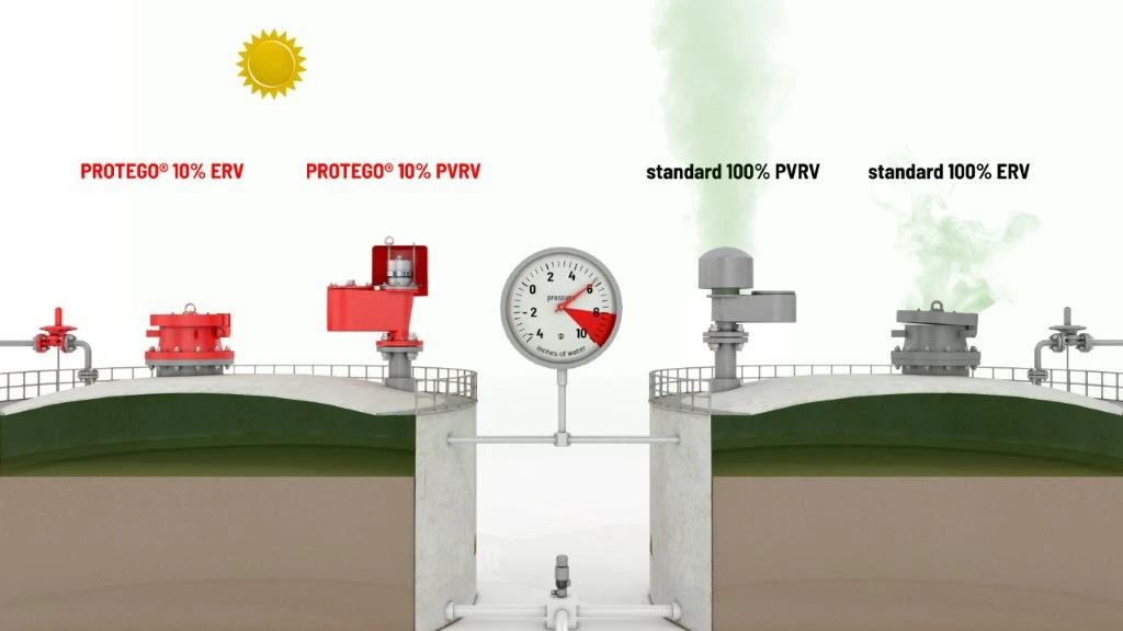
10% Technology
Extreme Tightness
Optimum Pressure Maintenance
High Flow Capacity
Used in Explosion Hazardous Areas
Sturdy Housing Design
Spring Loading (Overpressure Side)
Pressure and Vacuum Relief Valve with Flange Connection for a Vent Line
Full Lift Technology
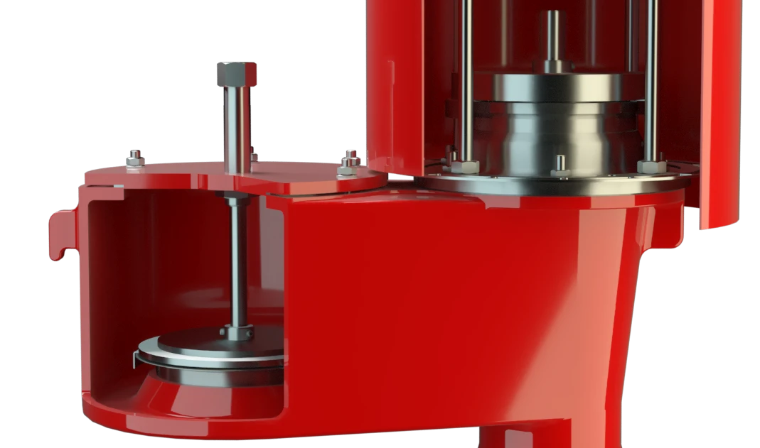
Optimized Valve Design for Maximum Performance
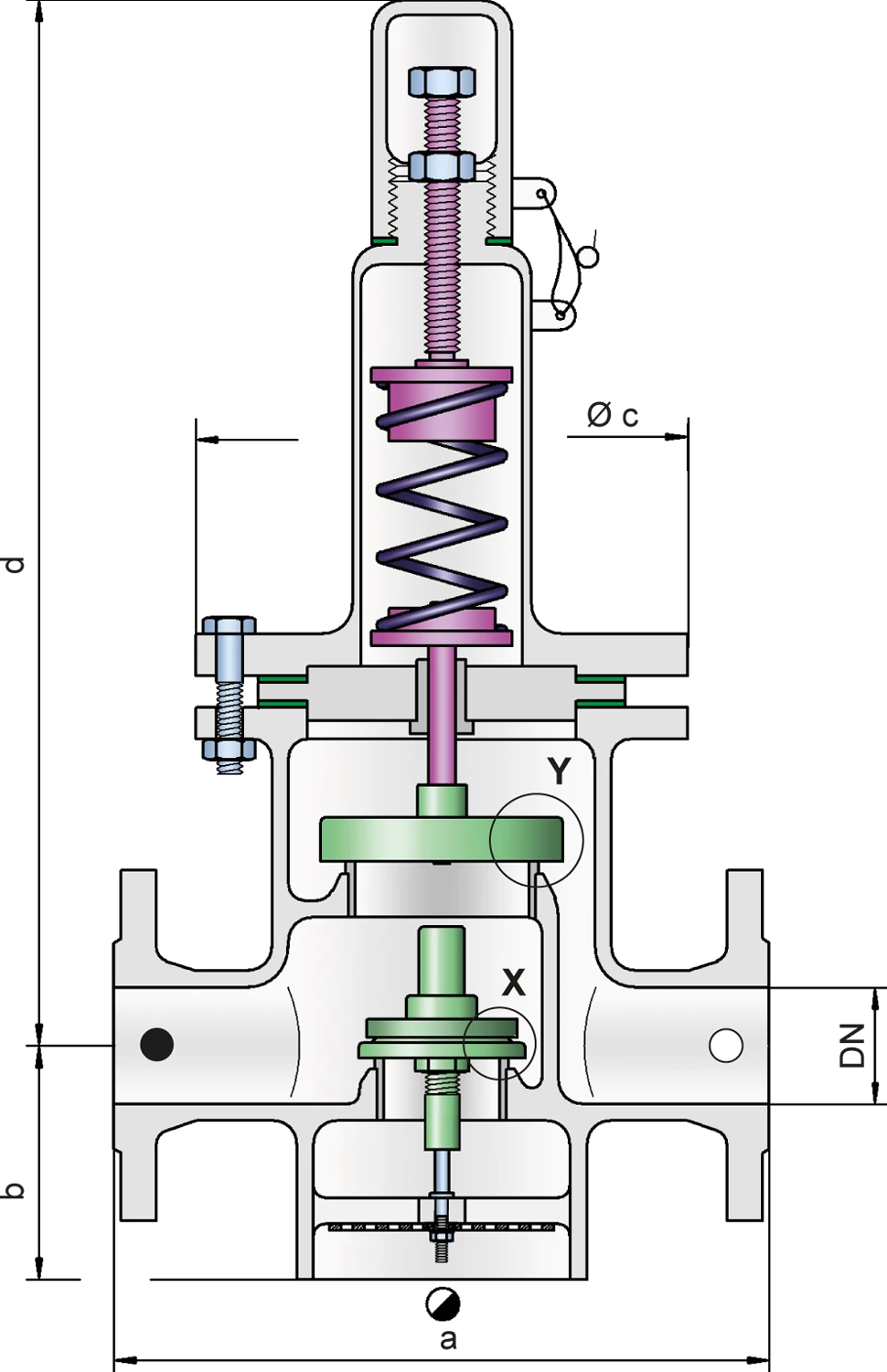
Dimensions
To select the nominal size (DN), please use the flow capacity charts on the following pages
| DN | 40 / 1½“ | 50 / 2" | 80 / 3" | 100 / 4" | 150 / 6" |
| a | 280 / 11.02 | 280 / 11.02 | 340 / 13.39 | 390 / 15.35 | 520 / 20.47 |
| b | 85 / 3.35 | 85 / 3.35 | 125 / 4.92 | 140 / 5.51 | 185 / 7.28 |
| c | 210 / 8.27 | 210 / 8.27 | 280 / 11.02 | 310 / 12.20 | 390 / 15.35 |
| d | 565 / 22.24 | 565 / 22.24 | 675 / 26.57 | 805 / 31.69 | 1070 / 42.13 |
Dimensions in mm / inches
Larger sizes upon request
Dimensions for pressure and vacuum relief valve with heating jacket upon request
Material selection for housing
| Design | A | B |
| Housing | Steel | Stainless Steel |
| Heating jacket (DV / ZW-F-H-...) | Steel | Stainless Steel |
| Valve seat | Stainless Steel | Stainless Steel |
| Gasket | PTFE | PTFE |
Option: Housing with ECTFE-lining
Special materials upon request
Material selection for pressure valve pallet
| Design | A |
| Pressure range [mbar] [inch W.C.] | >+60 up to +500 >+24 up to +200 |
| Valve pallet | Stainless Steel |
| Sealing | Metal to Metal |
| Spring | Stainless Steel |
Special materials upon request
For lower set pressure use type DV/ZW. Higher set pressure and lower set vacuum upon request.
Material selection for vacuum valve pallet
| Design | A* | B* | C | D |
| Pressure range [mbar] [inch W.C.] | -3,5 up to -5,0 -1.4 up to -2.0 | <-5,0 up to -14 <-2.0 up to -5.6 | <-14 up to -35 <-5.6 up to -14 | <-35 up to -50 <-14 up to -20 |
| Valve pallet | Aluminium | Stainless Steel | Stainless Steel | Stainless Steel |
| Sealing | FEP | FEP | Metal to Metal | Metal to Metal |
*by set pressure up to +150 mbar / inch W.C.
Special materials and lower set vacuum upon request.
Flange connection type
| EN 1092-1; Form B1 |
| ASME B16.5 CL 150 R.F. |
other types upon request
Flow Capacity Chart
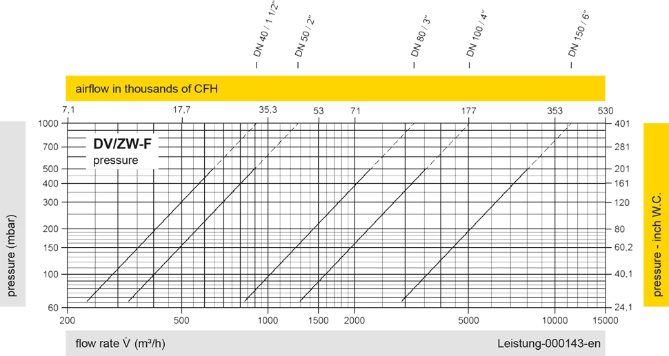
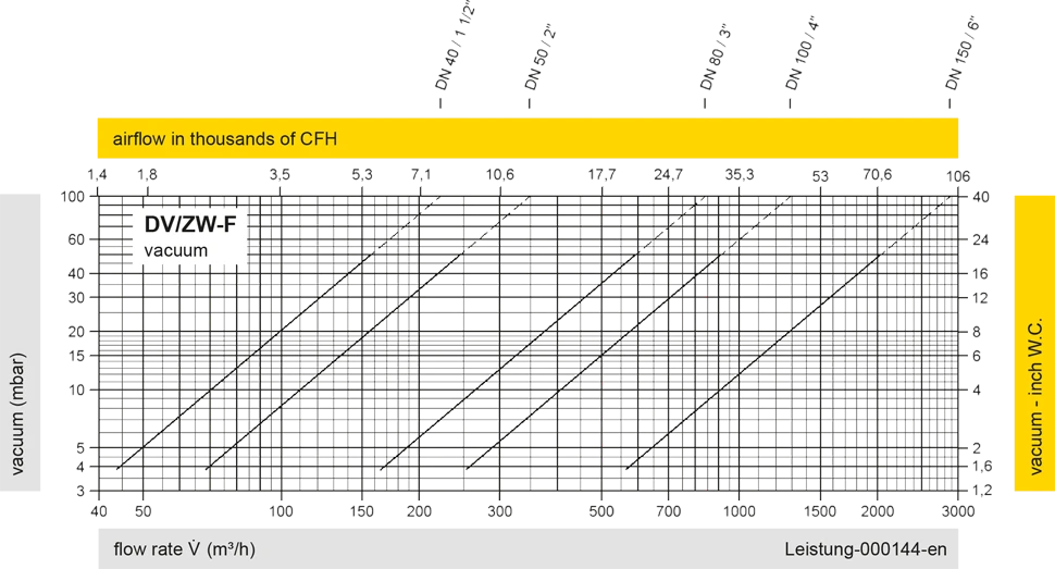
The flow capacity charts have been determined with a calibrated and TÜV certified flow capacity test rig. Volume flow V in (m³/h) and CFH refer to the standard reference conditions of air ISO 6358 (20°C, 1bar). For conversion to other densities and temperatures refer to Sec. 1: “Technical Fundamentals”.
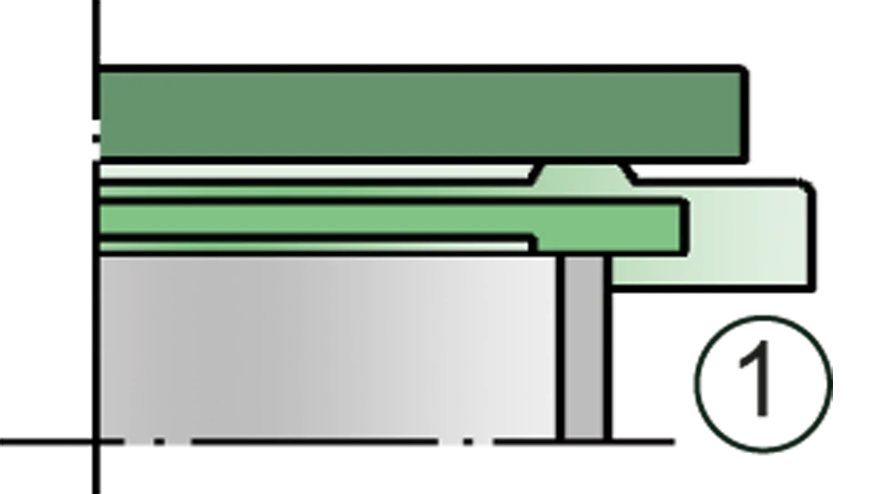
Detail X
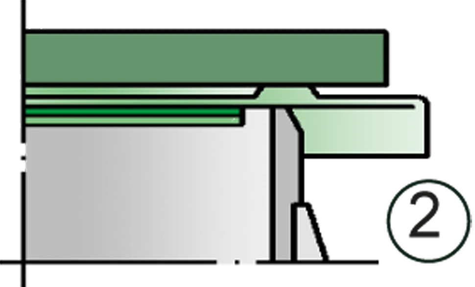
Detail X

Detail Y

Tank connection

Inbreathing

Outbreathing