DR/EU
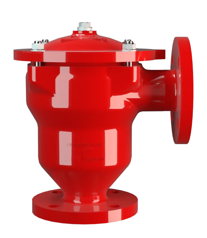
In-Line Detonation Flame Arrester for unstable and stable detonations and deflagrations in right angle design with a shock absorber, unidirectional
Features
Reduced Number of FLAMEFILTER® Discs
Fastest Disassembly and Assembly
Modular Design
Angle Bodied
Spare Parts
Provides Safety
Extended Application Range
Low Costs
Protects Against Deflagrations and Stable and Unstable Detonations
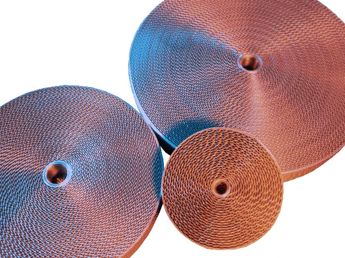
Main Component – PROTEGO® Flame Arrester Unit

Many Individual Certifications
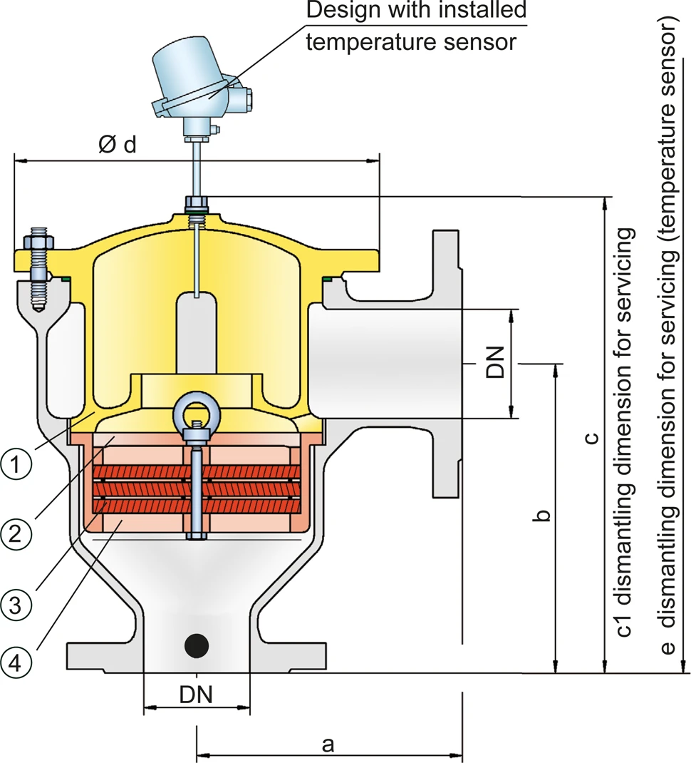
Dimensions
To select the nominal size (DN), please use the flow capacity charts on the following pages
| DN | 25 / 1" | 32 / 1¼“ | 40 / 1½“ | 50 / 2“ | 65 / 2½“ | 80 / 3" | 100 / 4" | 125 / 5" | 150 / 6" |
| a | 125 / 4.92 | 125 / 4.92 | 153 / 6.02 | 155 / 6.10 | 198 / 7.80 | 200 / 7.87 | 250 / 9.84 | 332 / 13.07 | 335 / 13.19 |
| b | 140 / 5.51 | 140 / 5.51 | 183 / 7.20 | 185 / 7.28 | 223 / 8.78 | 225 / 8.86 | 290 / 11.42 | 357 / 14.06 | 360 / 14.17 |
| c | 210 / 8.27 | 210 / 8.27 | 290 / 11.42 | 290 / 11.42 | 365 / 14.37 | 365 / 14.37 | 440 / 17.32 | 535 / 21.06 | 535 / 21.06 |
| c1 | 285 / 11.22 | 285 / 11.22 | 395 / 15.55 | 395 / 15.55 | 500 / 19.69 | 500 / 19.69 | 595 / 23.43 | 750 / 29.53 | 750 / 29.53 |
| d | 150 / 5.91 | 150 / 5.91 | 210 / 8.27 | 210 / 8.27 | 275 / 10.83 | 275 / 10.83 | 325 / 12.80 | 460 / 18.11 | 460 / 18.11 |
| e | 495 / 19.49 | 495 / 19.49 | 600 / 23.62 | 600 / 23.62 | 705 / 27.76 | 705 / 27.76 | 795 / 31.30 | 950 / 37.40 | 950 / 37.40 |
Dimensions in mm / inches
Selection of explosion group
| MESG | Expl. Gr. (IEC / CEN) | Gas Group (NEC) |
| > 0,90 mm | IIA | D |
| ≥ 0,65 mm | IIB3 | C |
Special approvals upon request
Selection of max. operating pressure
| Expl. Gr. | DN | 25 / 1" | 32 / 1¼" | 40 / 1½" | 50 / 2" | 65 / 2½" | 80 / 3" | 100 / 4" | 125 / 5" | 150 / 6" |
| IIA | Pmax | 1,6 / 23.3 | 1,6 / 23.3 | 1,6 / 23.3 | 1,6 / 23.3 | 1,6 / 23,.3 | 1,6 / 23.3 | 1,5 / 21.7 | 1,2 / 17.4 | 1,2 / 17.4 |
| IIB2 | Pmax | 1,4 / 20.3 | 1,4 / 20.3 | |||||||
| IIB3 | Pmax | 1,6 / 23.2 | 1,6 / 23.3 | 1,6 / 23.3 | 1,6 / 23.3 | 1,6 / 23.3 | 1,6 / 23.3 | 1,4 / 20.3 | 1,2* / 17.4 | 1,2* / 17.4 |
Pmax = maximum allowable operating pressure in bar / psi absolute, higher operating pressure upon request, * Special flame arrester unit
Specification of max. operating temperature
| ≤ 60°C / 140°F | Tmaximum allowable operating temperature in °C |
| - | Designation |
higher operating temperatures upon request
Material selection for housing
| Design | B | C | D | |
| Housing | Carbon Steel | Stainless Steel | Hastelloy | |
| Heating jacket (DR / EU-H-(T)-...) | Steel | Stainless Steel | Stainless Steel | |
| Cover with shock absorber | Steel | Stainless Steel | Hastelloy | |
| O-Ring | FPM* | PTFE | PTFE | |
| Flame arrester unit | A | C, D | E | Special materials upon request |
* for devices exposed to elevated temperatures above 150°C / 302°F (T150), gaskets made of PTFE.
The housing and cover with the shock absorber can also be delivered in steel with an ECTFE coating.
Material combinations of flame arrester unit
| Design | A | C | D | E |
| FLAMEFILTER® cage | Steel | Stainless Steel | Stainless Steel | Hastelloy |
| FLAMEFILTER®* | Stainless Steel | Stainless Steel | Hastelloy | Hastelloy |
| Spacer | Stainless Steel | Stainless Steel | Hastelloy | Hastelloy |
* the FLAMEFILTER® are also available in the materials Tantalum, Inconel, Copper, etc. when the listed housing and cage materials are used.
Special materials upon request
Flange connection type
| EN 1092-1; Form B1 |
| ASME B16.5 CL 150 R.F. |
Flow Capacity Chart
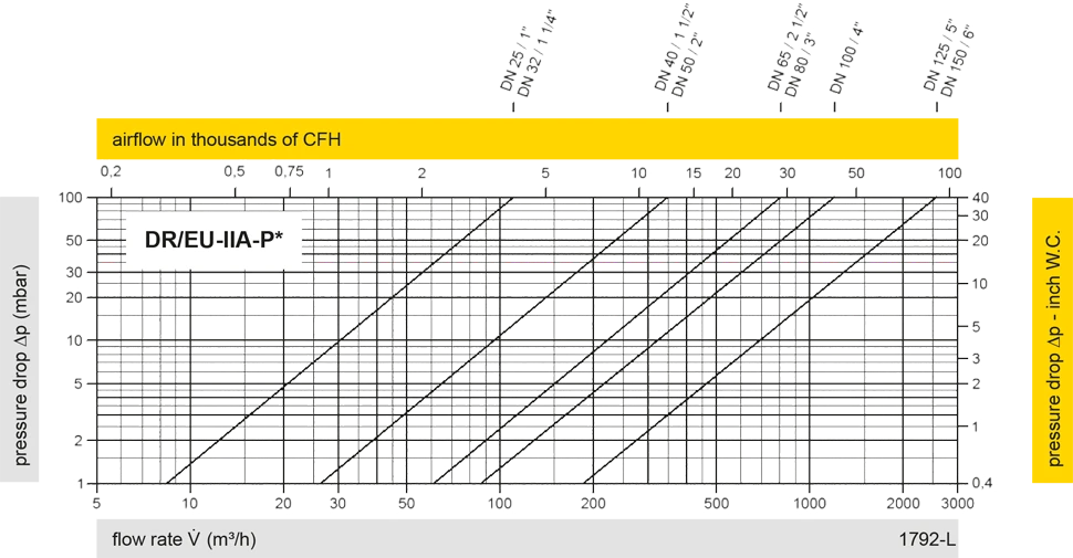
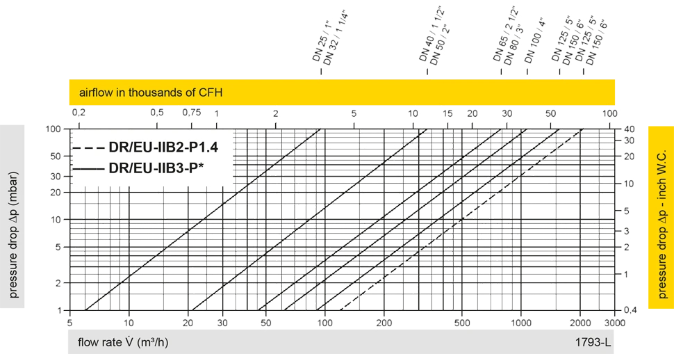
The flow capacity charts have been determined with a calibrated and TÜV certified flow capacity test rig. Volume flow V in (m³/h) and CFH refer to the standard reference conditions of air ISO 6358 (20°C, 1bar). For conversion to other densities and temperatures refer to Sec. 1: “Technical Fundamentals”.