FA-CN-IIA, IIB3
In-Line Deflagration Flame Arrester concentric design, bi-directional
Features
Compact Design
Eases Installation Close to Floors and Walls
Modular Design
Allows Replacement and Cleaning of Single FLAMEFILTER®
Bi-Directional Flame Transmission
Proof Design
Spare Parts
Cost-Effective Spare Parts
Provides Safety
Protects Against Deflagrations for All Explosion Groups IIA, IIB3 and IIC (NEC Groups D, C and B)
Extended Application Range
for Elevated Operating Temperatures and Pressures
Function and Description
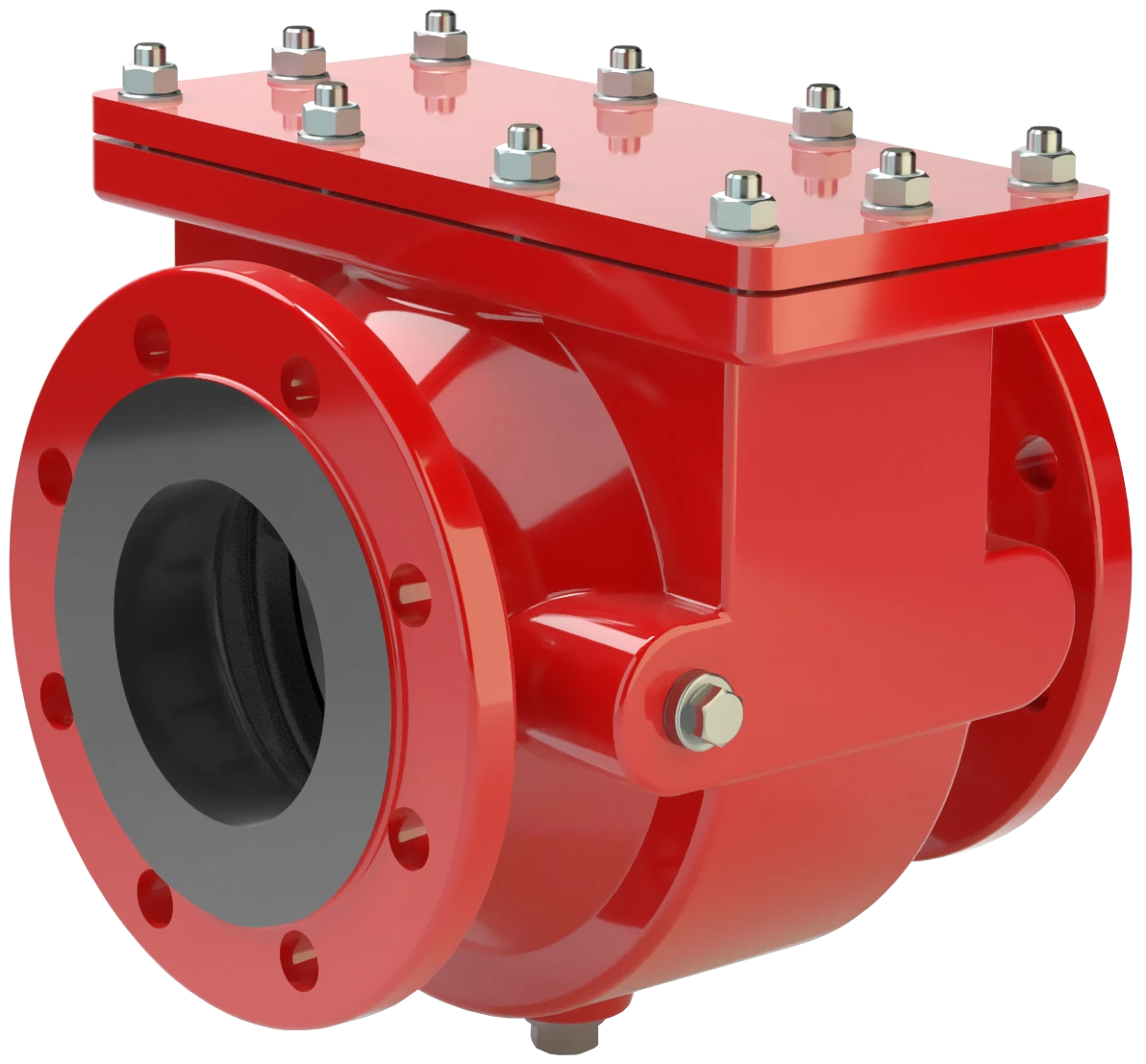
Compact and Maintenance-Friendly Design
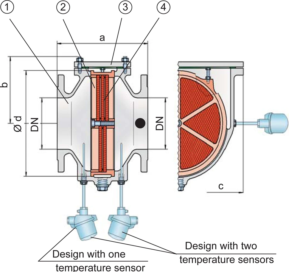
The PROTEGO® FA-CN In-Line Deflagration Flame Arrester is a compact design utilizing an easy access cover for easy maintenance. The PROTEGO® Flame Arrester Unit can easily be removed and cleaned in just a few simple steps without having to disassemble the pipe. When installing the Deflagration Flame Arrester, make sure that the distance between potential ignition sources and the location of the installed device does not exceed the L/D ratio (pipe length/pipe diameter) for which the device was tested. According to EN ISO 16852, this device is approved for a (L/D)max ratio of 50.
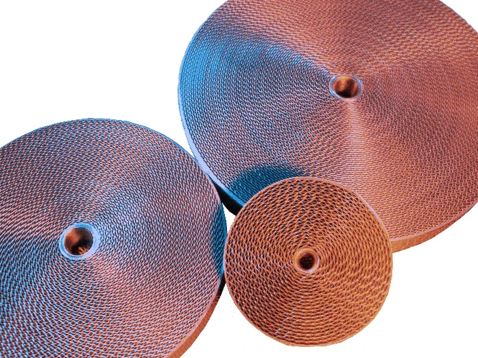
Main Component – PROTEGO® Flame Arrester Unit
The Deflagration Flame Arrester is symmetrical and offers bi-directional flame transmission protection. The device consists of the housing (1) with an easy access cover (3) and the PROTEGO® Flame Arrester Unit (2) in the center. The PROTEGO® Flame Arrester Unit is modular and consists of several FLAMEFILTER® discs (3) and spacers firmly held in a FLAMEFILTER® casing. The number of FLAMEFILTER® discs and their gap size depend on the device’s intended use.
For Explosion Groups IIA to IIC
Specifying the operating conditions, such as the temperature, pressure, explosion group, and the composition of the fluid, enables PROTEGO® to select the best Deflagration Flame Arrester for your application. This version of PROTEG® FA-CN-IIA and IIB3 Flame Arrester protects against deflagrations of fuel/air mixtures of explosion groups IIA and IIB 3 (NEC D and C {MESG ≥0.65 mm}). PROTEG® FA-CN devices for substances of explosion groups IIA1 and IIC (NEC group B) are shown on separate pages.
The standard design can be used with an operating temperature of up to +60°C / 140°F and an absolute operating pressure up to 1.1 bar / 15.9 psi. Devices with special approval for higher pressures (see table 3) and higher temperatures are available upon request.

Many Individual Certifications
EU conformity according to the currently valid ATEX directive. Approvals according to other national/international regulations on request.
Product Data
Dimensions
To select the nominal size (DN), use the flow capacity charts on the following pages
| DN | 25 / 1" | 32 / 1¼“ | 40 / 1½“ | 50 / 2" | 65 / 2½“ | 80 / 3" | 100 / 4" | 125 / 5" | 150 / 6" | 200 | 250 | 300 |
| a | 200 / 7.87 | 200 / 7.87 | 210 / 8.27 | 215 / 8.46 | 235 / 9.25 | 240 / 9.45 | 265 / 10.43 | 305 / 12.01 | 310 / 12.20 | 300 / 11.81 | 320 / 12.60 | 350 / 13.78 |
| b | 92 / 3.62 | 92 / 3.62 | 105 / 4.13 | 105 / 4.13 | 132 / 5.2 | 132 / 5.2 | 150 / 5.91 | 197 / 7.75 | 197 / 7.75 | 220 / 8.66 | 260 / 10.24 | 295 / 11.61 |
| c | 175 / 6.89 | 175 / 6.89 | 200 / 7.87 | 200 / 7.87 | 260 / 10.24 | 260 / 10.24 | 308 / 12.13 | 415 / 16.34 | 415 / 16.34 | 446 / 17.56 | 520 / 20.47 | 600 / 23.62 |
| d | 105 / 4.13 | 105 / 4.13 | 130 / 5.12 | 130 / 5.12 | 185 / 7.28 | 185 / 7.28 | 220 / 8.66 | 310 / 12.20 | 310 / 12.20 | 355 / 13.98 | 420 / 16.54 | 490 / 19.29 |
Dimensions in mm / inches
Selection of explosion group
| MESG | Expl. Gr. (IEC / CEN) | Gas Group (NEC) |
| > 0,90 mm | IIA | D |
| ≥ 0,65 mm | IIB3 | C |
Special approvals upon request
Selection of max. operating pressure
| Expl. Gr. | DN | 25 / 1" | 32 / ¼" | 40 / 1½" | 50 / 2" | 65 / 2½" | 80 / 3" | 100 / 4" | 125 / 5" | 150 / 6" | 200 / 8" | 250 / 10" | 300 / 12" | n |
| IIA | Pmax | 1,6 / 23.2 | 1,6 / 23.2 | 1,6 / 23.2 | 1,6 / 23.2 | 1,6 / 23.2 | 1,6 / 23.2 | 1,5 / 21.8 | 1,5 / 21.8 | 1,5 / 21.8 | 1,3 / 18.9 | 1,3 / 18.9 | 1,3 / 18.9 | 3 |
| IIB3 | Pmax | 1,6 / 23.2 | 1,6 / 23.2 | 1,6 / 23.2 | 1,6 / 23.2 | 1,6 / 23.2 | 1,6 / 23.2 | 1,6 / 23.2 | 1,6 / 23.2 | 1,6 / 23.2 | 1,6 / 23.2 | 1,6 / 23.2 | 1,6 / 23.2 | 3 |
P = maximum allowable operating pressure in bar / psi absolute, higher operating pressure upon request
n = number of FLAMEFILTER®
Specification of max. operating temperature
| ≤ 60°C / 140°F | Tmaximum allowable operating temperature in °C |
| - | Designation |
higher operating temperatures upon request
Material selection
| Design | A | B |
| Housing | Steel | Stainless Steel |
| Cover | Steel | Stainless Steel |
| Gasket | PTFE | PTFE |
| Flame arrester unit | Stainless Steel | Stainless Steel |
Special materials upon request
Flange connection type
| EN 1092-1; Form B1 |
| ASME B16.5 CL 150 R.F. |
other connections upon request
Flow Capacity Chart
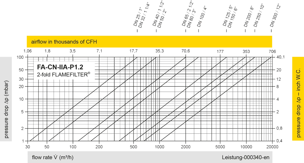
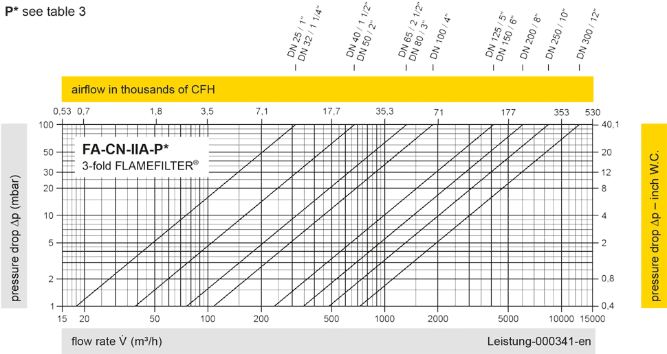
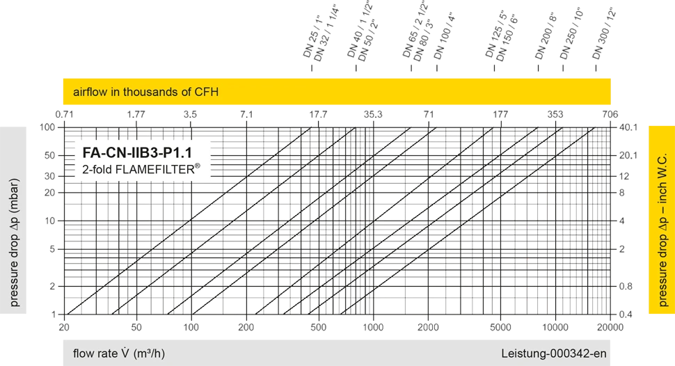
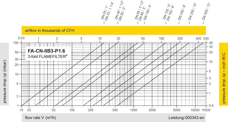
The flow capacity charts have been determined with a calibrated and TÜV certified flow capacity test rig. Volume flow V in (m³/h) and CFH refer to the standard reference conditions of air ISO 6358 (20°C, 1bar). For conversion to other densities and temperatures refer to Sec. 1: “Technical Fundamentals”.