PM/(D)S
Pressure/Vacuum Relief Valve Pilot-operated diaphragm valve
Features
High Level of Safety
Due to Double Pilot
Permanent Magnets
Controlled by Corrosion-Resistant Control Valve (Pilot Valve), Low-Temperature-Resistant Permanent Magnet
Pop-Open Characteristic
from the Lowest Pressure Increase up to Full Lift
Extreme Tightness
Resulting in Lowest Possible Product Losses and Reduced Environmental Pollution
Optimal Pressure Maintenance
Set Pressure Close to Opening Pressure for Optimum Pressure Maintenance in the System
Flow Capacity
Optimized Flow Capacity
Used in Explosion Hazardous Areas
can Be Used in Explosion Hazardous Areas
Low Temperature
Designed for Use at Low Temperatures
Condensate Drainage
Automatic Condensate Drain
Function and Description
Combined Pressure and Vacuum Relief Valve
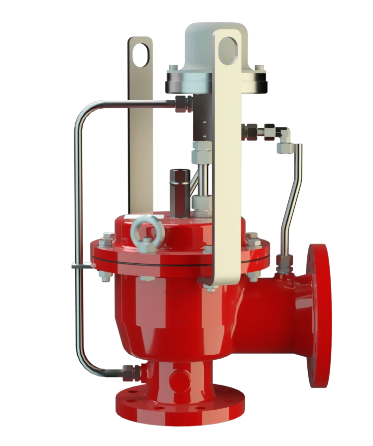
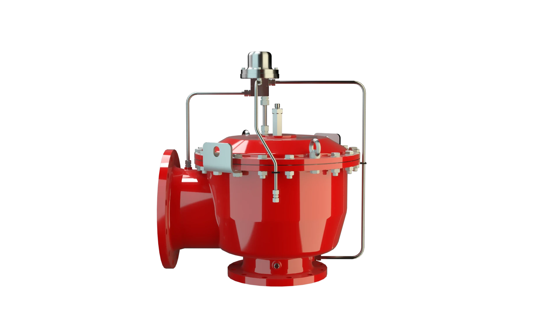
The PM/(D)S Pilot-Operated PROTEGO® diaphragm valve is a highly developed valve for pressure and vacuum relief. It is primarily used as a device for out-breathing in tanks, containers, and process equipment. It provides protection against unallowable overpressure and prevents the intake of air and unallowable product vapor loss up to the set pressure.
The valve can also be used as an in-breathing valve where the main valve is directly controlled when it is exposed to a vacuum, i.e., it functions as a weight-loaded diaphragm valve. It is ideally suitable for both atmospheric conditions and for use in low temperatures.
Corrosion-Resistant and Cryogenic Permanent Magnet
The main valve is controlled by a pilot valve. The pilot valve is controlled by the tank pressure. The tank substance does not continuously flow through the pilot. The set pressure is adjusted on the pilot valve by a corrosion-resistant and low-temperature resistant permanent magnet.
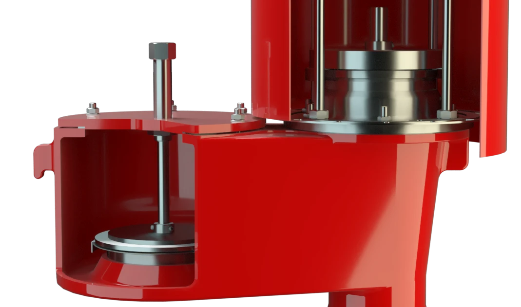
As the operating pressure increases, the closing force at the main valve also increases; i.e., the valve tightness increases until the set pressure is reached to prevent leakage.
Advanced Manufacturing Technology
After the valve responds, it immediately opens completely without any significant increase in pressure (Pop-Open Characteristic), and the nominal volumetric flow is released through a fully open valve. If this is exceeded, the pressure increase follows the volume flow (Δp/V̇ curve). The tank pressure is maintained up to the set pressure with a tightness that is above the normal standards due to our state-of-the art manufacturing. This feature is ensured by valve seats made of high quality stainless steel with precisely lapped valve pallets. After the overpressure is released or the vacuum is balanced, the valve re-seats and provides a tight seal.
Product Data
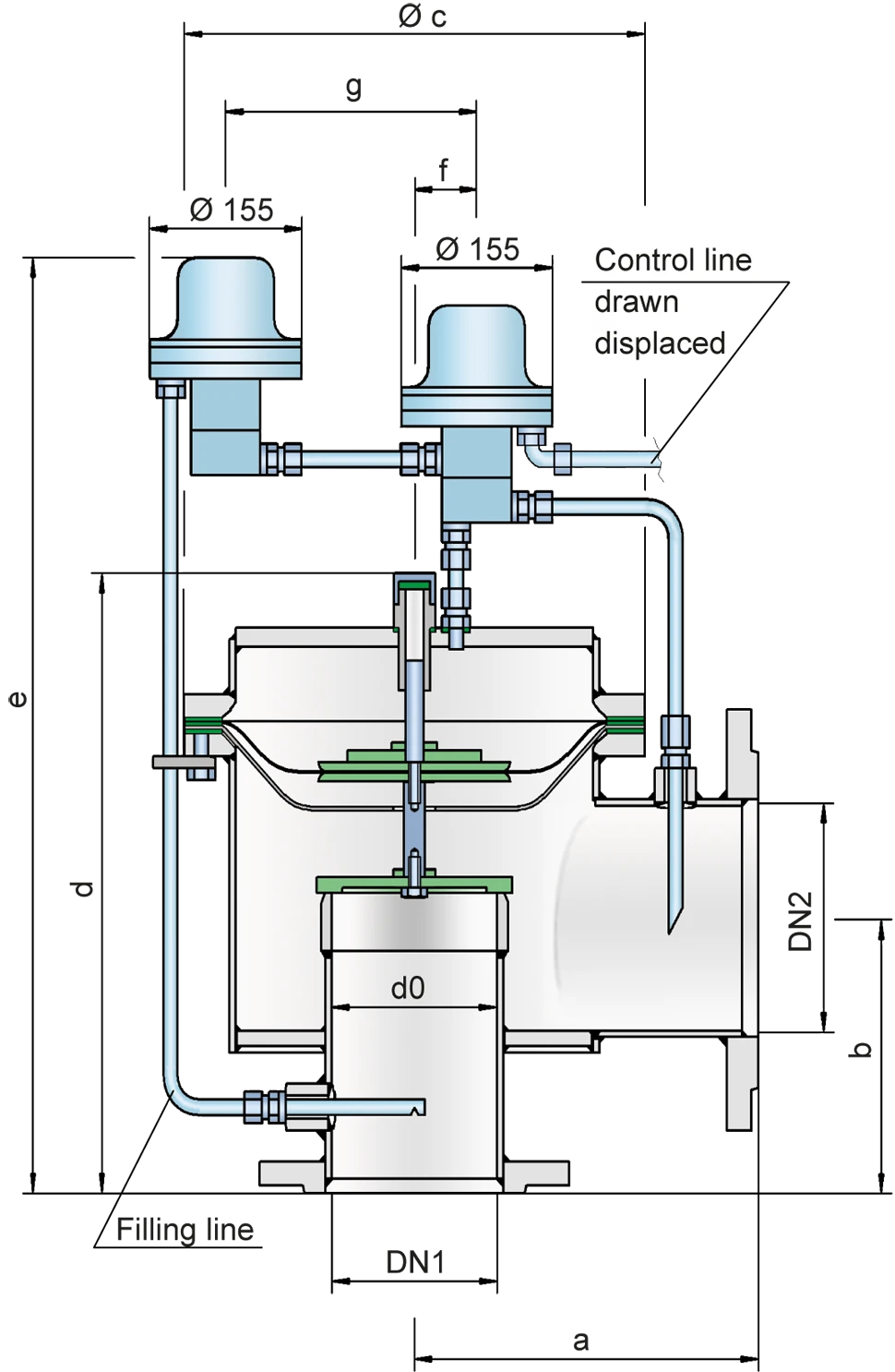
Dimensions
To select the nominal size (DN), use the flow capacity charts on the following pages
| DN1 | 80 / 3" | 100 / 4" | 150 / 6" | 200 / 8" | 250 / 10" | 300 / 12 | 300 / 12" |
| DN2 | 100 / 4" | 150 / 6" | 200 / 8" | 250 / 10" | 300 / 12" | 350 / 14" | 400 |
| a | 225 / 8.86 | 250 / 9.87 | 325 / 12.80 | 375 / 14.76 | 450 / 17.72 | 500 / 19.69 | 500 / 19.69 |
| b | 150 / 5.91 | 175 / 6.89 | 225 / 8.86 | 250 / 9.84 | 270 / 10.63 | 300 / 11.81 | 325 / 12.79 |
| c | 275 / 10.83 | 330 / 12.99 | 445 / 17.52 | 550 / 21.65 | 665 / 26.18 | 785 / 30.91 | 785 / 30.91 |
| d | 370 / 14.57 | 425 / 16.73 | 530 / 20.87 | 605 / 23.82 | 675 / 26.57 | 785 / 30.91 | 835 / 32.87 |
| e | 615 / 24.21 | 685 / 26.97 | 770 / 30.31 | 825 / 32.48 | 935 / 36.81 | 1005 / 39.57 | 1055 / 41.53 |
| f | 35 / 1.38 | 40 / 1.57 | 40 / 1.57 | 50 / 1.97 | 50 / 1.97 | 50 / 1.97 | 50 / 1.97 |
| g | 160 / 6.30 | 195 / 7.68 | 250 / 9.84 | 315 / 12.40 | 370 / 14.57 | 425 / 16.73 | 425 / 16.73 |
Dimensions in mm / inches
Material selection for housing
| Design | A | B |
| Housing | Aluminium | Stainless Steel |
| Valve seat | Stainless Steel | Stainless Steel |
| Sealing | KL-C-4106 | KL-C-4106 |
| Main diaphragm protection | Stainless Steel | Stainless Steel |
| Pilot lines | Stainless Steel | Stainless Steel |
| Pilot housing | Stainless Steel | Stainless Steel |
| Pilot diaphragm | FEP | FEP |
Special materials upon request
Material selection for valve pallet
| Design | A | B | C |
| Pressure range [mbar] [inch W.C.] | -3,0 up to -4* -1.2 up to -1.6* | -4,0 up to -5,0* -1.6 upm to -2.0* | -5,0 up to -7,0* -2.0 up to -2,8* |
| Valve pallet | Aluminium | Stainless Steel | Stainless Steel |
| Diaphragm | FEP | FEP | FEP |
| Diaphragm pallet | Aluminium | Aluminium | Stainless Steel |
* The indicated vacuum ranges depend on the nominal size and can differ. The pressure Setting can be combined with any vacuum setting
Special materials upon request
Flange connection type
| EN 1092-1; Form B1 |
| ASME B16.5 CL 150 R.F. |
other types upon request
Flow Capacity Chart
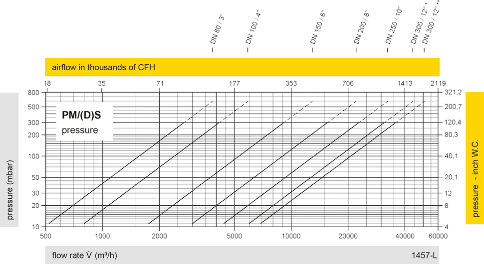
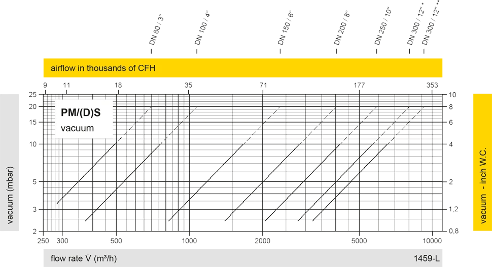
The flow capacity charts have been determined with a calibrated and TÜV certified flow capacity test rig. Volume flow V in (m³/h) and CFH refer to the standard reference conditions of air ISO 6358 (20°C, 1bar). For conversion to other densities and temperatures refer to Sec. 1: “Technical Fundamentals”.