UB/VF
Vacuum Diaphragm Valve deflagration-proof
Features
Extreme Tightness
Resulting in Lowest Possible Product Losses and Reduced Environmental Pollution
Optimal Pressure Maintenance
Set Pressure Close to Opening Pressure for Optimum Pressure Maintenance in the System
Flow Capacity
Optimized Flow Capacity
Digital Level Monitoring
Digital Level Monitoring Available to Optimize Maintenance Intervals
Digital Level Sensors
Digital Level Sensors Can Be Retrofitted to Installed Valves
Condensate Drainage
Automatic Condensate Drain
Monitoring
Monitoring of the Load Liquid by Level Indicator
Easy Operation Monitoring
and Maintenance by Simply Opening the Hinged Valve Cap
Modular Design
Allows Replacement and Cleaning of Single FLAMEFILTER®
Suitable for Challenging Applications
Particularly Suitable for Problematic Products Such as Styrene, Acrylates, etc.
Protective System According to ATEX
can Be Used as a Protective System in Areas With Potentially Explosive Atmosphere in Accordance With ATEX
Frost-Proof
Optimal Frost Protection
Function and Description
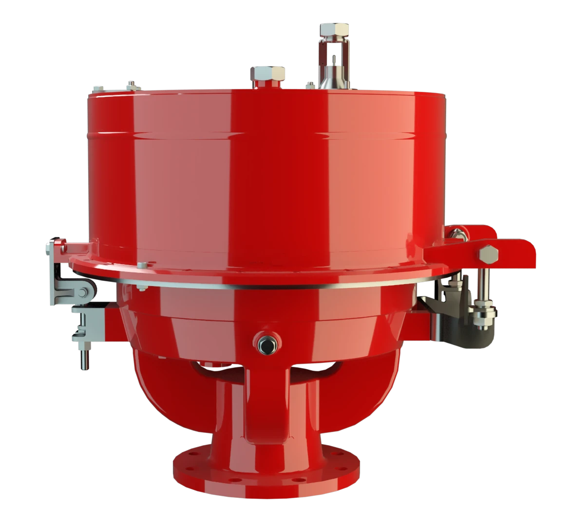
Highly Developed Vacuum Relief Valve
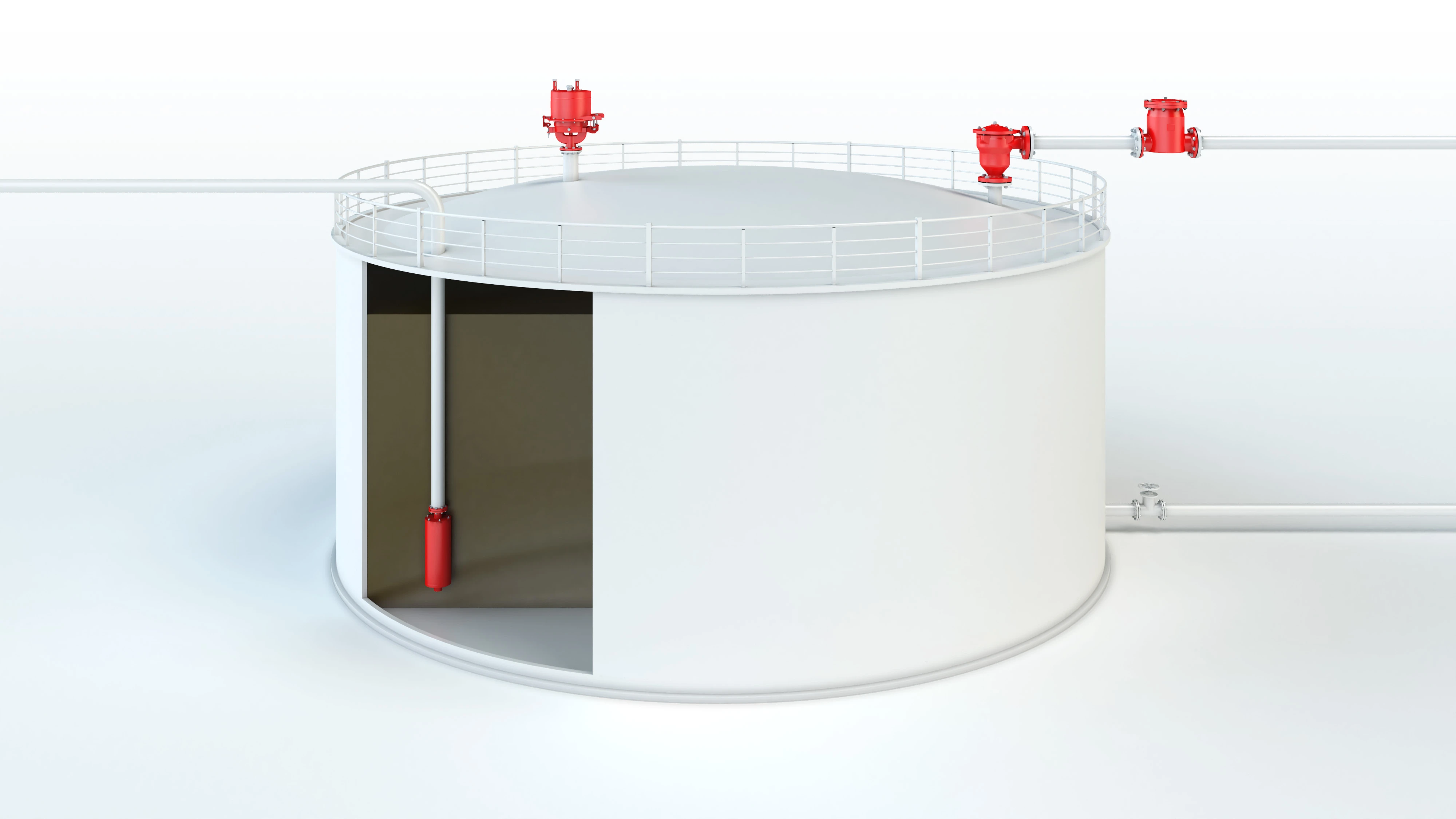
The PROTEGO® UB/VF diaphragm valve is a worldwide unique vacuum relief valve combining the function of a dynamic and static Flame Arrester. It is primarily used as a device for flame transmission-proof in-breathing on tanks, containers, and process equipment. The valve offers reliable protection against vacuum build up, prevents the in-breathing of air and product losses almost up to the set vacuum, and protects against atmospheric deflagration.
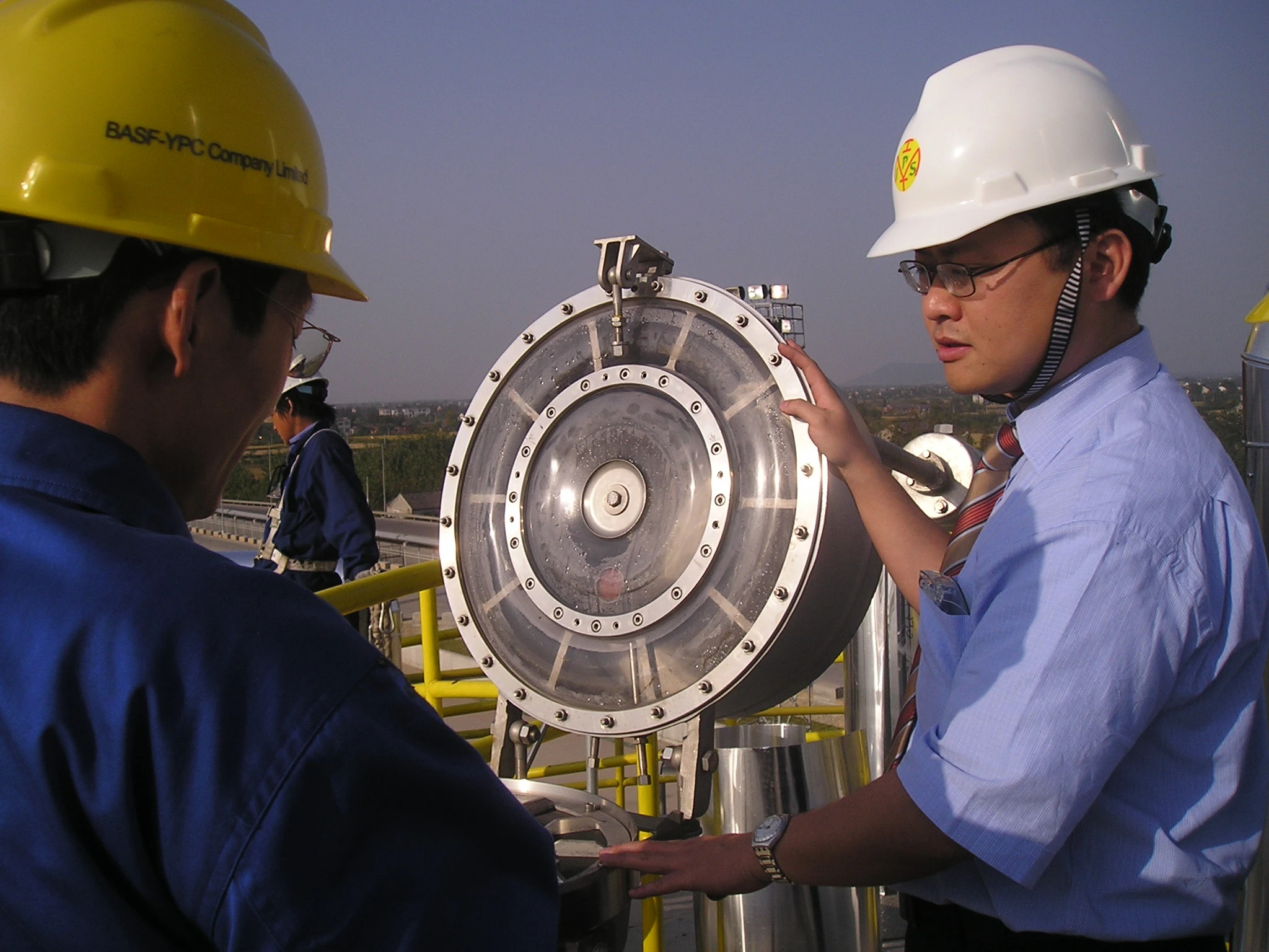
High Operational Reliability in Extreme Conditions
The PROTEGO® UB/VF diaphragm valve has proven itself over many years under a wide variety of operating conditions in the mineral oil and chemical industries. Worldwide, it is the only vent which works reliably with problem products such as styrene or acrylates. The set vacuum is adjusted with a freeze resistant water-glycol mixture which ensures safe operation under extreme cold weather conditions. The PROTEGO® UB/VF valve is available for substances from explosion group IIB3.
Composition
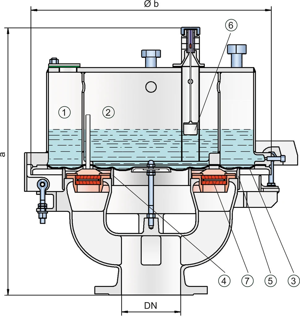
If a vacuum builds up in the tank, it is transmitted through pressure balancing tubes into the vacuum chambers (1), (2), which are connected to each other. This will remove the weight of the load liquid, and the atmospheric pressure will lift the diaphragm (3) off the inner and outer valve seat rings (4, 5), resulting in ventilation of the tank. The vacuum setting is adjusted via the filling level of the load liquid and can be checked by a floating level indicator (6).
Advanced Manufacturing Technology
The tank vacuum is maintained up to the set vacuum with a tightness that is above the normal standards due to our highly developed manufacturing technology. This is achieved by the liquid loaded diaphragm pressing tightly around the special designed valve seat surface area even when the operating vacuum increases, which reduces surface pressure and unnecessary leakage. After the vacuum is balanced, the valve re-seats and provides a tight seal.
Main Component – PROTEGO® Flame Arrester Unit
At very low vacuum settings, the explosion pressures resulting from an atmospheric deflagration may be strong enough to lift the diaphragm off the valve seat rings. The ignition into the tank can be prevented by installing the PROTEGO® Flame Arrester Unit (7). This PROTEGO® Flame Arrester Unit provides additional protection against atmospheric deflagration when the valve is open for maintenance and inspection. The valve can be used at an operating temperature of up to +60°C/ 140°F and meets the requirements of European Tank Design Standard EN 14015 (Appendix L) and ISO 28300 (API 2000). EU conformity according to the currently valid ATEX directive. Approvals according to other national/international regulations on request.
Product Data
Dimensions
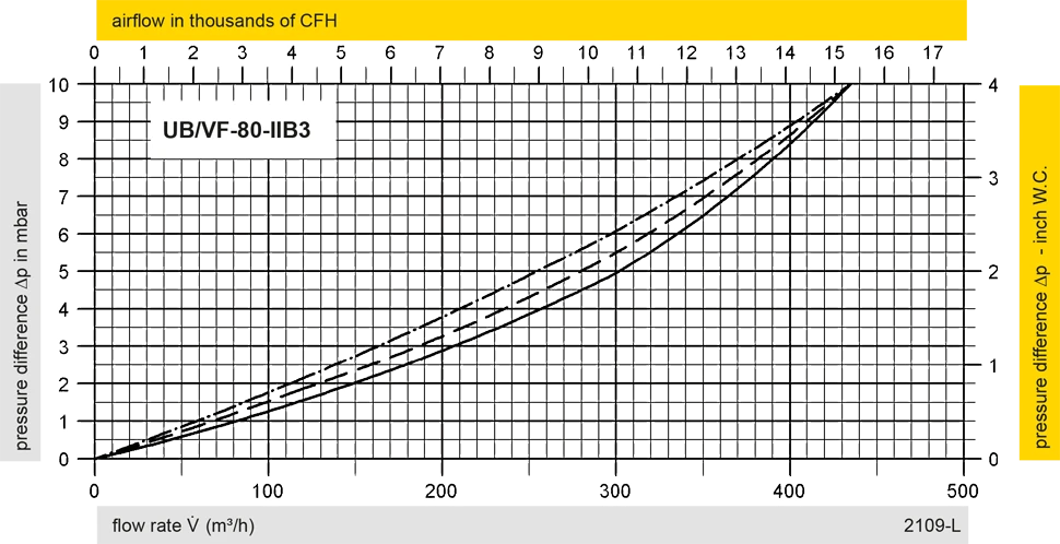
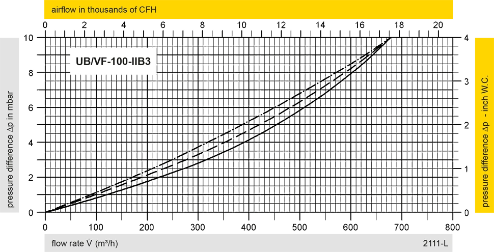
To select the nominal size (DN), please use the flow capacity charts on the following pages
| DN | vacuum | vacuum | 80 / 3" | vacuum | vacuum | 100 / 4" | 150 / 6" |
| a | up to -28 mbar | up to -11.2 inch W.C. | 615 / 24.21 | up to -22 mbar | up to -8.8 inch W.C. | 645 / 25.39 | 680 / 26.77 |
| a | < -28 mbar | < -11.2 inch W.C. | 765 / 31.12 | < -22 mbar | < -8.8 inch W.C. | 795 / 31.30 | 830 / 32.68 |
| b | 410 / 16.14 | 485 / 19.09 | 590 / 23.23 |
Dimensions in mm / inches
Dimensions for vacuum diaphragm valve with heating coil upon request
Selection of explosion group
| MESG | Expl. Gr. (IEC / CEN) | Gas Group (NEC) |
| ≥ 0,65 mm | IIB3 | C |
Special approvals upon request
Material selection for housing
| Design | C | D |
| Housing | Cast Iron | Stainless Steel |
| Valve top | Stainless Steel | Stainless Steel |
| Heating coil (UB / VF-H-...) | Stainless Steel | Stainless Steel |
| Valve seat | Stainless Steel | Stainless Steel |
| Gasket | FPM | PTFE |
| Diaphragm | A, B | A, B |
| Flame arrester unit | A | C |
Option: Housing with ECTFE-lining
Special materials upon request
Material selection
| Design | A | B |
| Diaphragm | FPM | FEP |
Special materials upon request
Material combinations of flame arrester unit
| Design | C |
| FLAMEFILTER® cage | Stainless Steel |
| FLAMEFILTER® | Stainless Steel |
| Spacer | Stainless Steel |
Special materials upon request
Flange connection type
| EN 1092-1; Form B1 |
| ASME B16.5 CL 150 R.F. |
other types upon request
Flow Capacity Chart
UB/VF DN100 Vacuum
UB/VF DN150 Vacuum
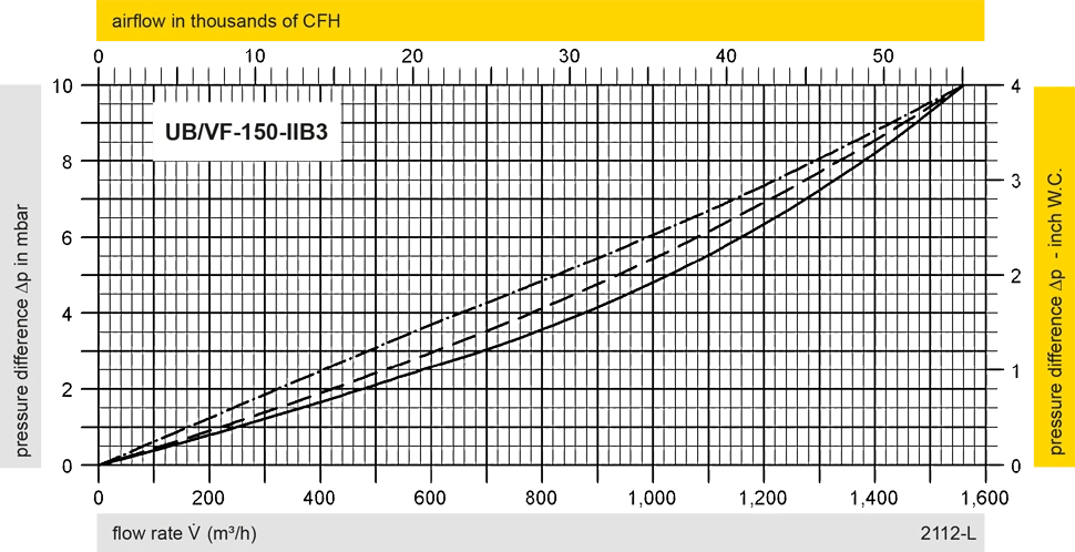
The flow capacity charts have been determined with a calibrated and TÜV certified flow capacity test rig. Volume flow V in (m³/h) and CFH refer to the standard reference conditions of air ISO 6358 (20°C, 1bar). For conversion to other densities and temperatures refer to Sec. 1: “Technical Fundamentals”.