DR/SV
In-Line Detonation Flame Arrester with shut-off valve, for stable detonations and deflagrations in a straight through design, unidirectional
Features
Fácil manutenção
Desmontagem e montagem mais rápidas
Design modular
Segurança contra explosões
Peças de reposição
Desligamentos de emergência
Bombas de vácuo
Detonation Arrester With the Advantages of a Shut-Off Valve
Suction-Side Protection for Compressors and Pumps

For Explosion Group IIA
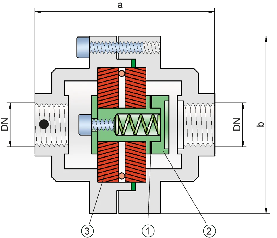
Tabela de dimensões
Para selecionar o diâmetro nominal (DN), utilize os diagramas de vazão nas páginas seguintes
| DN | G ½" | G ¾" |
| a | 115 | 115 |
| b | 100 | 100 |
Dimensões em mm
Seleção do grupo de explosão
| MESG | Gr. expl. (IEC / CEN) | Grupo gás (NEC) |
| > 0,90 mm | IIA | D |
Aprovações especiais sob solicitação
Seleção da pressão máx. de trabalho
| DN | G ½" | G ¾" |
| Pmáx. | 1,1 | 1,1 |
Pmáx. = pressão de trabalho máxima admissível em bar absoluta, pressão de trabalho mais elevada sob solicitação
Indicação da temperatura máx. de trabalho
| ≤ 60°C / 140°F | Ttemperatura máxima de trabalho admissível em °C |
| - | Designation |
temperaturas de trabalho mais elevadas, sob solicitação
Seleção do material do corpo
| Versão | A | B |
| Corpo | Latão | Aço inoxidável |
| Vedação | WS 3822 | WS 3822 |
| Conjunto abafador de chamas | A | A, B |
Materiais especiais sob solicitação
Combinações de material do conjunto abafador de chamas
| Design | A | B |
| FLAMEFILTER®* | Stainless Steel | Stainless Steel |
| Spacer | Stainless Steel | Stainless Steel |
| Support for FLAMEFILTER® | Brass | Stainless Steel |
| Washer | Brass | Stainless Steel |
* the FLAMEFILTER® are also available in the materials Tantalum, Inconel, Copper, etc. when the listed housing and cage materials are used.
Special materials upon request
Tipo de conexão
| Rosca para tubo DIN ISO 228-1 | DIN |
Outras conexões roscadas sob solicitação
Diagrama de vazão
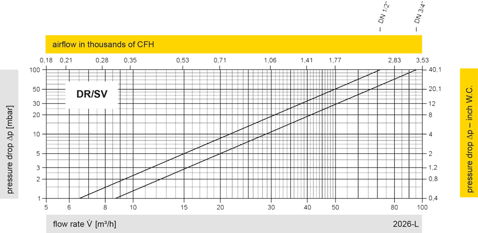
Este diagrama de vazão foi determinado em uma bancada de medição de vazão calibrada e certificada pela TÜV. A vazão V em m³/h se refere ao estado técnico padrão de ar, conforme ISO 6358 (20°C, 1bar). Para conversão em outras densidades e temperaturas, veja o cap. 1: Bases técnicas.