FA-G-IIA1-P2.2
In-Line Deflagration Flame Arrester for biogas, sewage gas and landfi ll gas, concentric design, bidirectional, endurance burning proof (under atmospheric conditions)

Features
Design modular
Desmontagem e montagem mais rápidas
Conexão roscada para tubulação
Propagação bidirecional de chama
Garante segurança
Peças de reposição
Protection of Fuel Supply Lines
For Explosion Group IIA1 - Methan

Many Individual Certifications
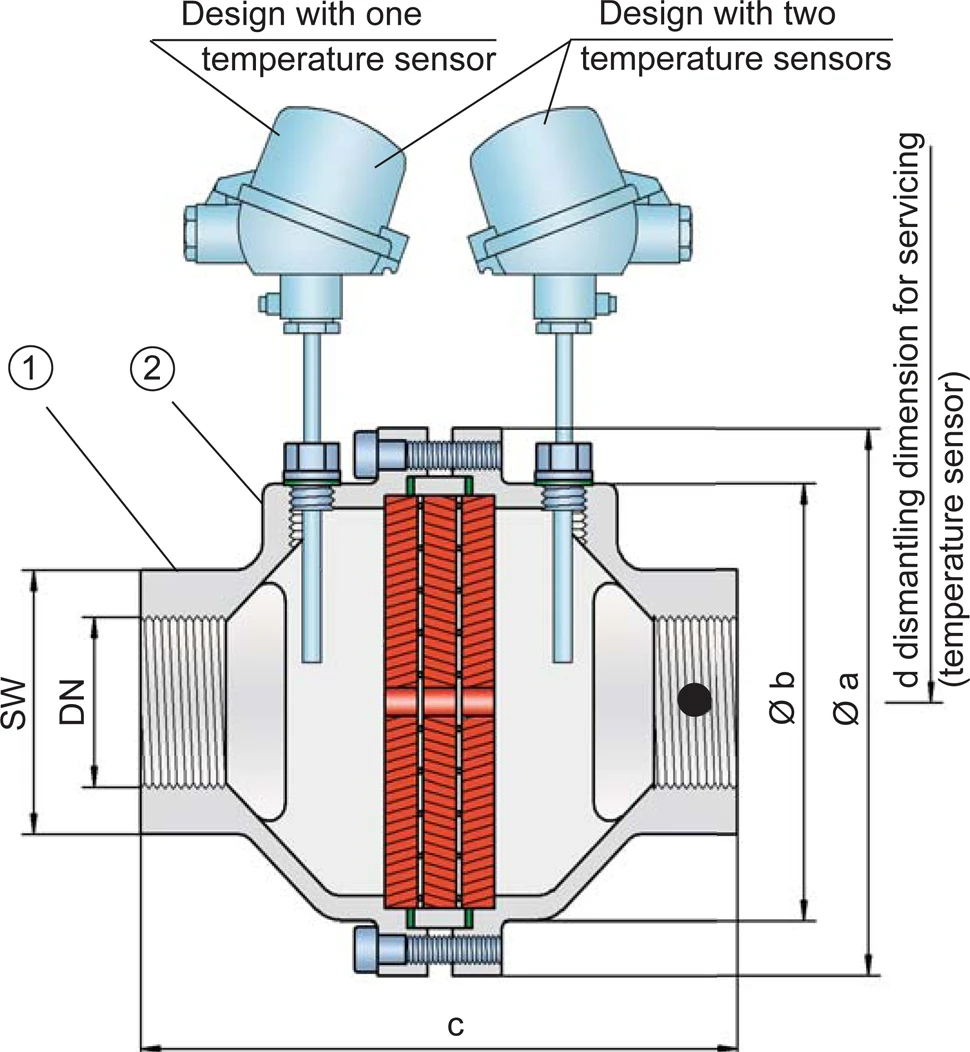
Tabela de dimensões
Para escolher o diâmetro nominal (DN), veja os diagramas de vazão nas páginas seguintes
| DN | G ½ | G ¾ | G 1 | G 1 ¼ | G 1 ½ | G 2 |
| a | 80 | 80 | 100 | 100 | 155 | 155 |
| b | 55 | 55 | 76 | 76 | 124 | 124 |
| c | 10 | 100 | 110 | 110 | 170 | 170 |
| d | — | — | -— | — | 400 | 400 |
| SW | 32 | 32 | 50 | 50 | 75 | 75 |
Dimensions in mm / inches, SW= width across flats
Seleção do grupo de explosão
| MESG | Gr. expl. (IEC / CEN) |
| ≥ 1,14 mm | IIA1 |
Aprovações especiais sob solicitação
Seleção da pressão máx. de trabalho
| Expl. Gr | DN | G ½ | G ¾ | G 1 | G 1 ¼ | G 1 ½ | G 2 |
| IIA1 | Pmax | 2,2 | 2,2 | 2,2 | 2,2 | 2,2 | 2,2 |
Pmáx. = pressão de trabalho máxima admissível em bar absoluta, pressão de trabalho mais elevada sob solicitação
Indicação da temperatura máx. de trabalho
| ≤ 60°C / 140°F | Ttemperatura máxima de trabalho admissível em °C |
| - | Designation |
temperaturas de trabalho mais elevadas, sob solicitação
Seleção do material
| Execução | B | C |
| Corpo | Aço inoxidável | Hastelloy |
| Vedação | PTFE | PTFE |
| FLAMEFILTER®* | Aço inoxidável | Hastelloy |
* os FLAMEFILTER® também podem ser fornecidos em tântalo, Inconel, cobre etc., em caso de utilização dos materiais do corpo listados.
Materiais especiais sob solicitação.
Tipo de conexão
| Rosca para tubo DIN ISO 228-1 | DIN |
outras conexões roscadas sob solicitação
Diagrama de vazão
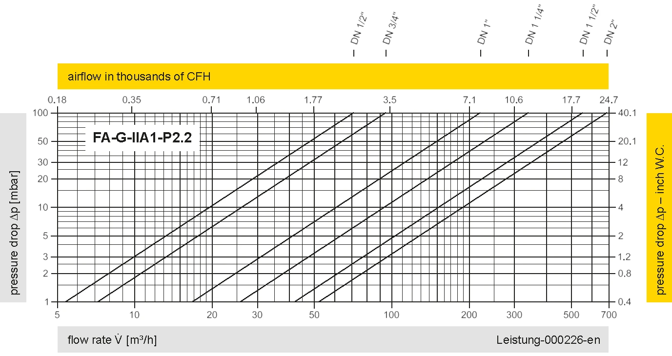
Este diagrama de vazão foi determinado em uma bancada de medição de vazão calibrada e certificada pela TÜV. A vazão V em m³/h se refere ao estado técnico padrão de ar, conforme ISO 6358 (20°C, 1bar). Para conversão em outras densidades e temperaturas, veja o cap. 1: Bases técnicas.