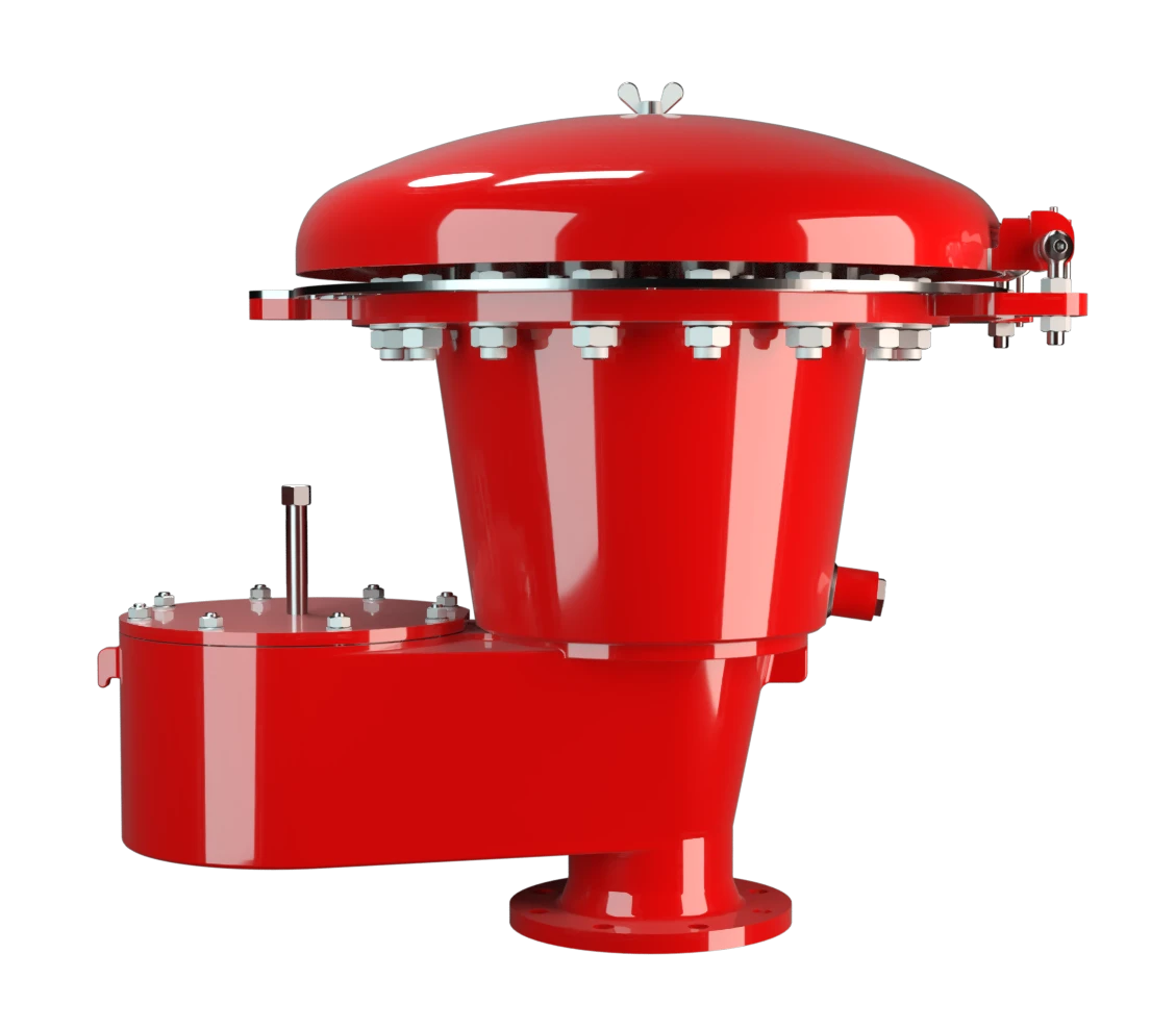
VD-SV-EB
Pressure/Vacuum Relief Valve deflagration- and endurance burning-proof
Features
Tecnologia de 10%
Estanqueidade extrema
Manutenção ideal da pressão
Abertura e fechamento mais eficientes
Disco da válvula guiado
Sistema de proteção conforme ATEX
Segurança contra combustão prolongada
Design modular
Corta-chamas integrado
Combined Pressure and Vacuum Relief Valve
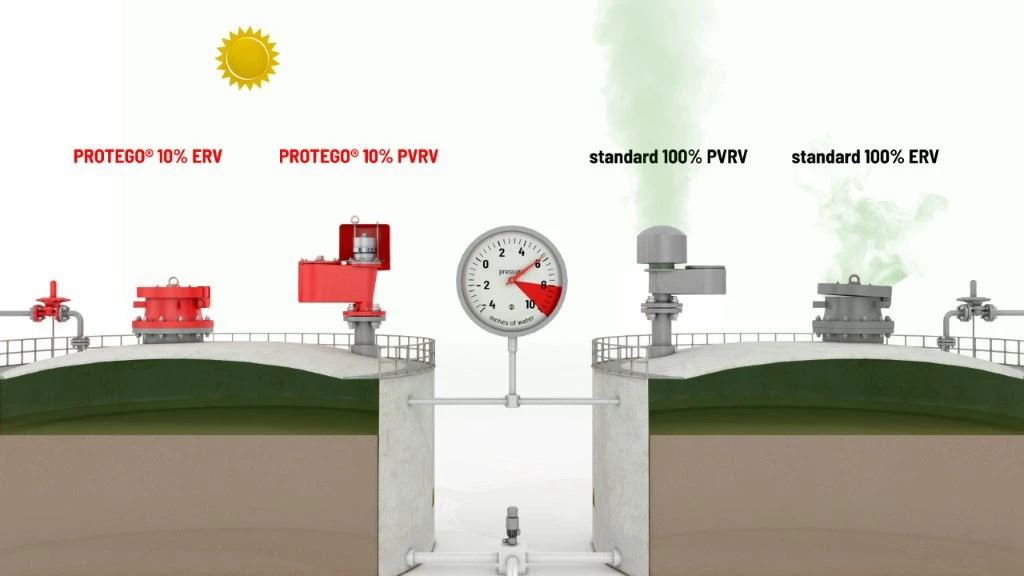
10%-Technology
Advanced Manufacturing Technology
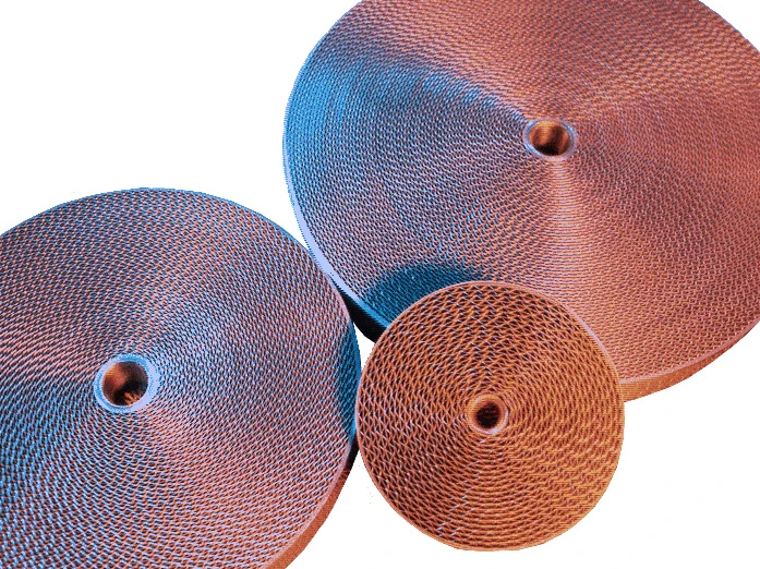
Main Component – PROTEGO® Flame Arrester Unit

Many Individual Certifications
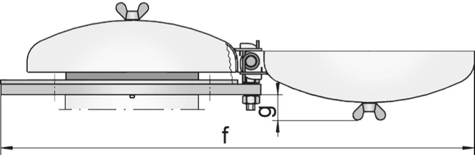
Tabela de dimensões
Para escolher o diâmetro nominal (DN), veja os diagramas de vazão nas páginas seguintes
| DN | DN2 | a | b | c | d | e | f | g |
| 150 / 6“ | 400 / 16“ | 705 / 27.76 | 844 / 33.23 | 802 / 31.57 | 957 / 37.68 | 235 / 9.25 | 1500 / 59.06 | 109 / 4.29 |
| 200 / 8“ | 400 / 16“ | 705 / 27.76 | 939 / 36.97 | 802 / 31.57 | 1027 / 40.43 | 235 / 9.25 | 1500 / 59.06 | 109 / 4.29 |
Dimensões em mm
Dimensions for pressure valves with heating jacket upon request
Seleção do grupo de explosão
| MESG | Expl. Gr. (IEC / CEN) | Gas Group (NEC) |
| > 0,90 mm | IIA | D |
Special approvals upon request
Seleção do material do corpo
| Design | B | C |
| Housing | Steel | Stainless Steel |
| Heating jacket (VD-SV-EB-H-...) | Steel | Stainless Steel |
| Valve seats | Stainless Steel | Stainless Steel |
| Gasket | PTFE | PTFE |
| Flange ring | Steel | Stainless Steel |
| Weather hood | Steel | Stainless Steel |
| Flame arrester unit | A | A, B |
Special materials upon request
Combinações de material do conjunto abafador de chamas
| Design | A | B |
| FLAMEFILTER® cage | Steel | Stainless Steel |
| FLAMEFILTER® | Stainless Steel | Stainless Steel |
| Safety bar | Stainless Steel | Stainless Steel |
Special materials upon request
Seleção do material do disco da válvula de pressão
| Design | A | B | C | D | E | F |
| Pressure range [mbar] [inch W.C.] | +2.0 up to +3.5 +0.8 up to +1.4 | >+3.5 up to +14 >+1.4 up to +5.6 | >+14 up to +35 >+5.6 up to +14 | >+35 up to +60 >+14 up to +24 | >+14 up to +35 >+5.6 up to +14 | >+35 up to +60 >+14 up to +24 |
| Valve pallet | Aluminium | Stainless Steel | Stainless Steel | Stainless Steel | Stainless Steel | Stainless Steel |
| Sealing | FEP | FEP | Metal to Metal | Metal to Metal | PTFE | PTFE |
Special material as well as higher set pressure upon request
Seleção do material do disco da válvula de vácuo
| Design | A | B | C | D | E | F |
| Vacuum range [mbar] [inch W.C.] | -2.0 up to -3.5 -0.8 up to -1.4 | <-3.5 up to -14 <-1.4 up to -5.6 | <-14 up to -35 <-5.6 up to -14 | <-14 up to -35 <-5.6 up to -14 | <-35 up to -60 <-14 up to -24 | <-35 up to -60 <-14 up to -24 |
| Valve pallet | Aluminium | Stainless Steel | Stainless Steel | Stainless Steel | Stainless Steel | Stainless Steel |
| Sealing | FEP | FEP | Metal to Metal | PTFE | Metal to Metal | PTFE |
Special material as well as higher set pressure upon request
Tipo de conexão flangeada
| EN 1092-1; Form B1 |
| ASME B16.5 CL 150 R.F. |
other types upon request
Diagrama de vazão
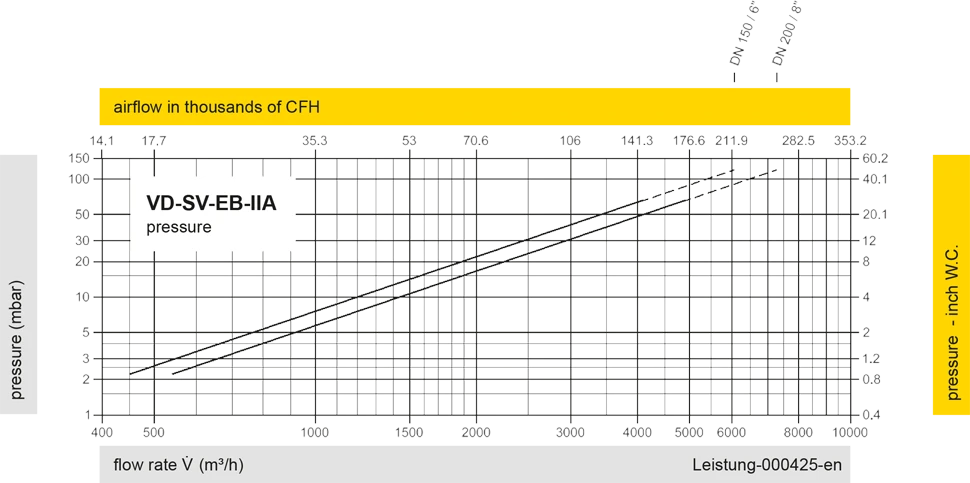
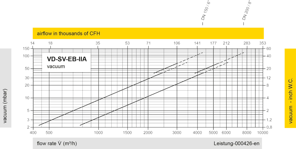
Este diagrama de vazão foi determinado em uma bancada de medição de vazão calibrada e certificada pela TÜV. A vazão V em m³/h se refere ao estado técnico padrão de ar, conforme ISO 6358 (20°C, 1bar). Para conversão em outras densidades e temperaturas, veja o cap. 1: Bases técnicas.
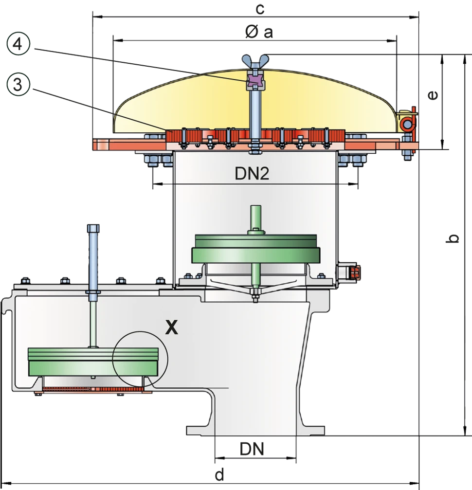
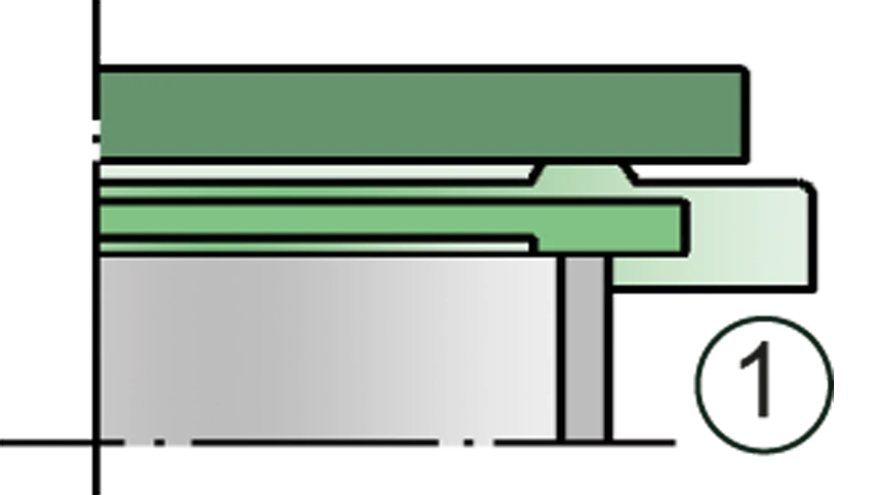
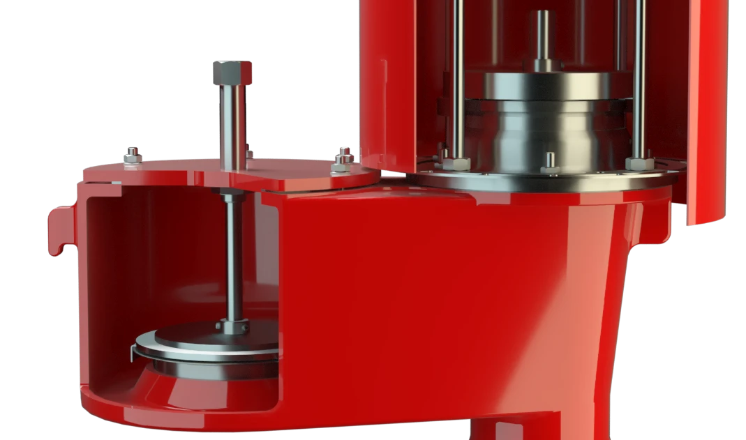
Detail X
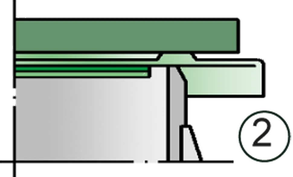
Einzelheit X