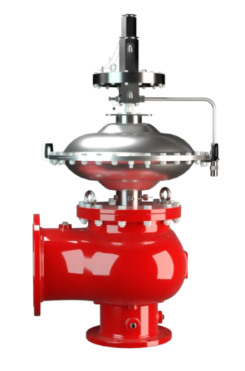
VN-A-PCPF
Pressure/Vacuum Relief Valve, Pilot-operated diaphragm valve
Features
Operado por piloto
Controlado por válvula de controle resistente à corrosão (válvula piloto)
Baixas emissões
Pequenas quantidades da substância armazenada no tanque são liberadas para a atmosfera quando a válvula é aberta
Tecnologia de 10%
para aumento mínimo de pressão até a abertura total
Estanqueidade extrema
Resulta nas menores perdas possíveis de produto e na redução do impacto ambiental
Manutenção ideal da pressão
Pressão de ajuste próxima à pressão de abertura para manutenção ideal da pressão no sistema
Alta durabilidade
Proteção do diafragma de controle da válvula principal contra baixas temperaturas, garantindo alta durabilidade
Capacidade de vazão
Capacidade de vazão otimizada
Uso em áreas com risco de explosão
Pode ser utilizado em áreas com risco de explosão
Kit de teste de campo
Conexão para teste de campo e kit disponíveis sob consulta
Function and Description
Combined Pressure and Vacuum Relief Valve
The PROTEGO® Type VN-A-PCPF pilot-controlled diaphragm valve is a newly developed valve for pressure and vacuum relief. It is primarily used as a device for out-breathing in tanks, containers, and process equipment. It provides protection against vacuum and overpressure and prevents the intake of air and unallowable product vapor loss up to the set pressure. The valve can also be used as an in-breathing valve where the main valve is directly controlled when it is exposed to a vacuum, i.e., it functions as a weight-loaded diaphragm valve.
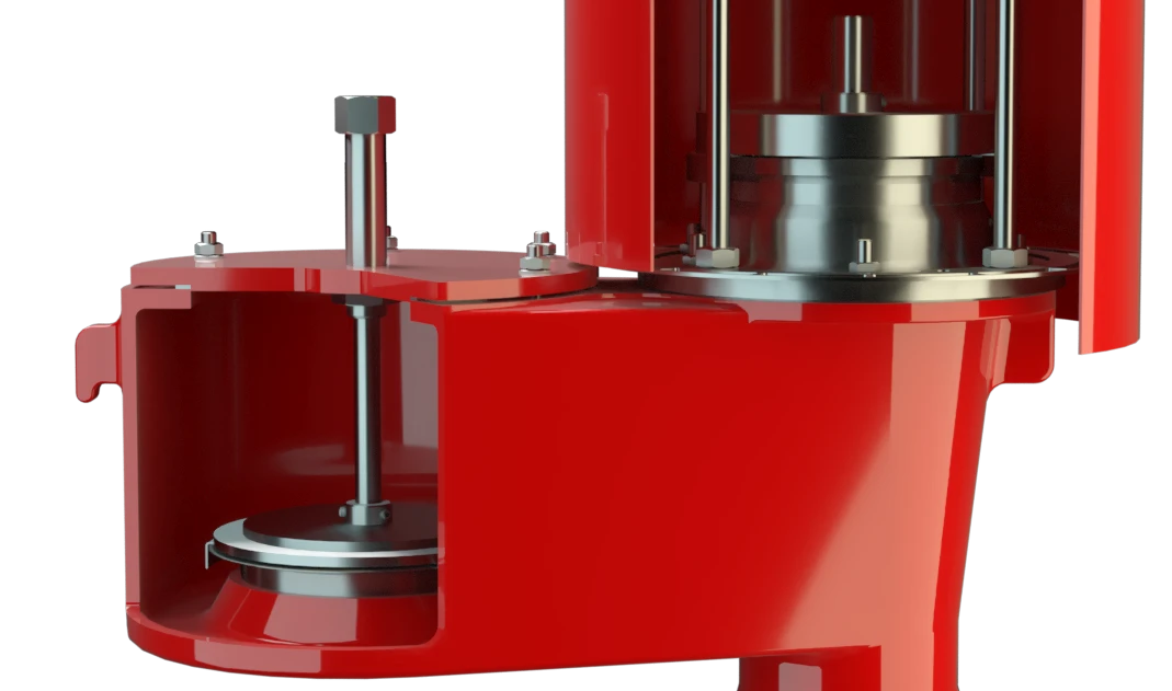
Tank Pressure Controls the Pilot Valve
The main valve is controlled by a pilot valve which is controlled by the tank pressure. A small amount of vapor is released into the atmosphere by the pilot valve when the valve opens. The set pressure is adjusted by increasing or decreasing the tension on the spring on the pilot valve.
Extreme Thightness
As the pressure increases, the closing force on the main valve increases, i.e., the valve becomes tighter with increasing tank pressure until the set pressure is reached. Once the valve has started to lift, it opens fully within a 10% of the pressure increase or opening pressure difference, and the nominal volume flow is released through a fully open valve. If and when this level is exceeded, the pressure increase will follow the performance curve (Δp/V. curve). From set pressure to full capacity (fully open valve), the pressure increase is 100% in case of vacuum venting/in-breathing function.
Advanced Manufacturing Technology
The tank pressure is maintained up to the set pressure with a tightness that is above the normal standards due to our highly developed manufacturing technology. This feature is ensured by valve seats made of high quality stainless steel with precisely lapped valve discs. After the overpressure is released or the vacuum is balanced, the valve re-seats and provides a tight seal.
Product Data
Tabela de dimensões
To select the nominal size (DN), use the flow capacity charts on the folloeing pages
| DN1 | DN2 | a | b | c | d | e | f | g |
| 50 / 2" | 50 / 2" | 175 / 6.89 | 175 / 6.89 | 170 / 6.69 | 360 / 14.17 | 916 / 36.06 | 205 / 8.07 | 343 / 13.53 |
| 50 / 2" | 80 / 3" | 175 / 6.89 | 175 / 6.89 | 170 / 6.69 | 360 / 14.17 | 931 / 36.65 | 205 / 8.07 | 358 / 14.09 |
| 80 / 3" | 80 / 3" | 200 / 7.87 | 200 / 7.87 | 205 / 8.07 | 360 / 14.17 | 957 / 37.68 | 205 / 8.07 | 383 / 15.08 |
| 80 / 3" | 100 / 4" | 200 / 7.87 | 200 / 7.87 | 205 / 8.07 | 360 / 14.17 | 967 / 38.07 | 205 / 8.07 | 393 / 15.47 |
| 100 / 4" | 100 / 4" | 225 / 8.86 | 225 / 8.86 | 250 / 9.84 | 360 / 14.17 | 991 / 39.02 | 205 / 8.07 | 418 / 16.46 |
| 100 / 4" | 150 / 6" | 225 / 8.86 | 225 / 8.86 | 250 / 9.84 | 360 / 14.17 | 1001 / 39.41 | 205 / 8.07 | 428 / 16.85 |
| 150 / 6" | 150 / 6" | 300 / 11.81 | 250 / 9.84 | 335 / 13.19 | 500 / 19.69 | 1104 / 43.46 | 275 / 10.83 | 503 / 19.80 |
| 150 / 6" | 200 / 8" | 300 / 11.81 | 250 / 9.84 | 335 / 13.19 | 500 / 19.69 | 1124 / 44.25 | 275 / 10.83 | 523 / 20.59 |
| 200 / 8" | 200 / 8" | 375 / 14.77 | 300 / 11.81 | 410 / 16.14 | 630 / 24.80 | 1237 / 48.70 | 340 / 13.39 | 610 / 24.02 |
| 200 / 8" | 250 / 10" | 375 / 14.77 | 300 / 11.81 | 410 / 16.14 | 630 / 24.80 | 1267 / 49.88 | 340 / 13.39 | 640 / 25.20 |
| 250 / 10" | 250 / 10" | 425 / 16.73 | 350 / 13.78 | 500 / 19.69 | 790 / 31.10 | 1357 / 53.43 | 420 / 16.54 | 710 / 27.96 |
| 250 / 10" | 300 / 12" | 425 / 16.73 | 350 / 13.78 | 500 / 19.69 | 790 / 31.10 | 1377 / 54.41 | 420 / 16.54 | 730 / 28.74 |
| 300 / 12" | 300 / 12" | 500 / 19.69 | 400 / 15.75 | 570 / 22.44 | 920 / 36.22 | 1468 / 57.80 | 485 / 19.09 | 803 / 31.61 |
| 300 / 12" | 350 / 14" | 500 / 19.69 | 400 / 15.75 | 570 / 22.44 | 920 / 36.22 | 1488 / 58.59 | 485 / 19.09 | 823 / 32.40 |
| 300 / 12" | 400 / 16" | 500 / 19.69 | 400 / 15.75 | 570 / 22.44 | 920 / 36.22 | 1508 / 59.37 | 485 / 19.09 | 843 / 33.19 |
Dimensões em mm
Seleção do material do corpo
| Design | A | B | C |
| Housing | Aluminium | Stainless Steel | LTCS* (Low Temperature Carbon Steel) |
| Valve seat | Stainless Steel | Stainless Steel | Stainless Steel |
| Sealing - housing | PTFE | PTFE | PTFE |
| Sealing – valve disc | metal - to - metal | metal - to - metal | metal - to - metal |
| Housing diaphragm | Stainless Steel | Stainless Steel | Stainless Steel |
| Pilot lines | Stainless Steel | Stainless Steel | Stainless Steel |
| Pilot housing | Aluminium | Aluminium/ Stainless Steel | Aluminium/ Stainless Steel |
| Pilot diaphragm | FEP | FEP | FEP |
* Special materials upon request
Tipo de conexão flangeada
| EN 1092-1; Form B1 |
| ASME B16.5 CL 150 R.F. |
Other types upon request
Coefficient of Discharge
| DN1 | 50 / 2" | 50 / 2" | 80 / 3" | 80 / 3" | 100 / 4" | 100 / 4" | 150 / 6" | 150 / 6" | 200 / 8" | 200 / 8" | 250 / 10" | 250 / 10" | 300 / 12" | 300 / 12" | 300 / 12" |
| DN2 | 50 / 2" | 80 / 3" | 80 / 3" | 100 / 4" | 100 / 4" | 150 / 6" | 150 / 6" | 200 / 8" | 200 / 8" | 250 / 10" | 250 / 10" | 300 / 12" | 300 / 12" | 350 / 14" | 400 / 16" |
| d0 | 54 / 2.13 | 54 / 2.13 | 83 / 3.27 | 83 / 3.27 | 108 / 4.25 | 108 / 4.25 | 160 / 6.30 | 160 / 6.30 | 208 / 8.19 | 208 / 8.19 | 262 / 10.31 | 262 / 10.31 | 310 / 12.20 | 310 / 12.20 | 310 / 12.20 |
| K | 0.57 | 0.83 | 0.75 | 0.79 | 0.69 | 0.85 | 0.7 | 0.8 | 0.65 | 0.8 | 0.62 | 0.76 | 0.62 | 0.72 | 0.8 |
DN1 = size inlet
DN2 = size outlet
d0 = orifice diameter(mm / inches)
K = coefficient of discharge
Diagrama de vazão
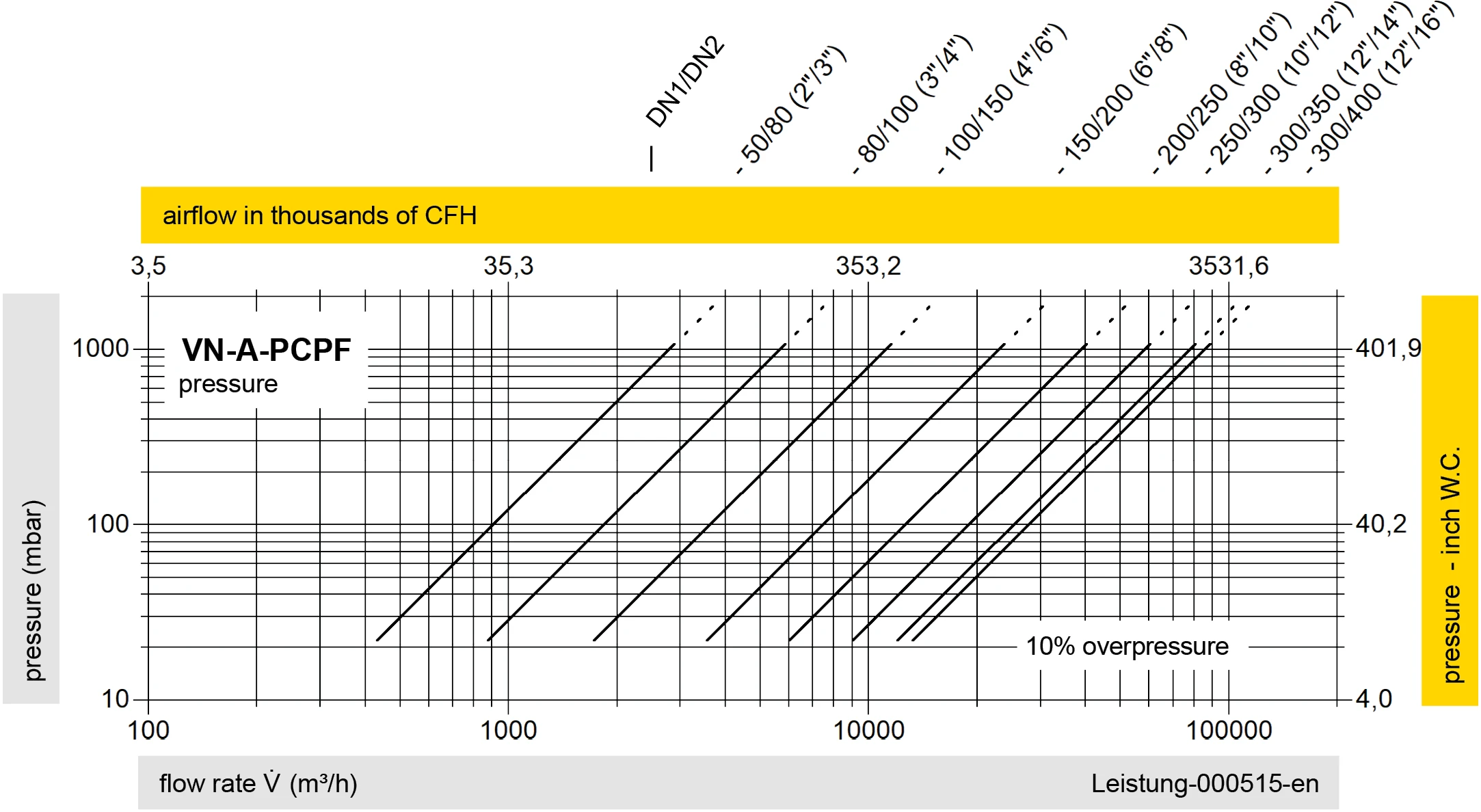
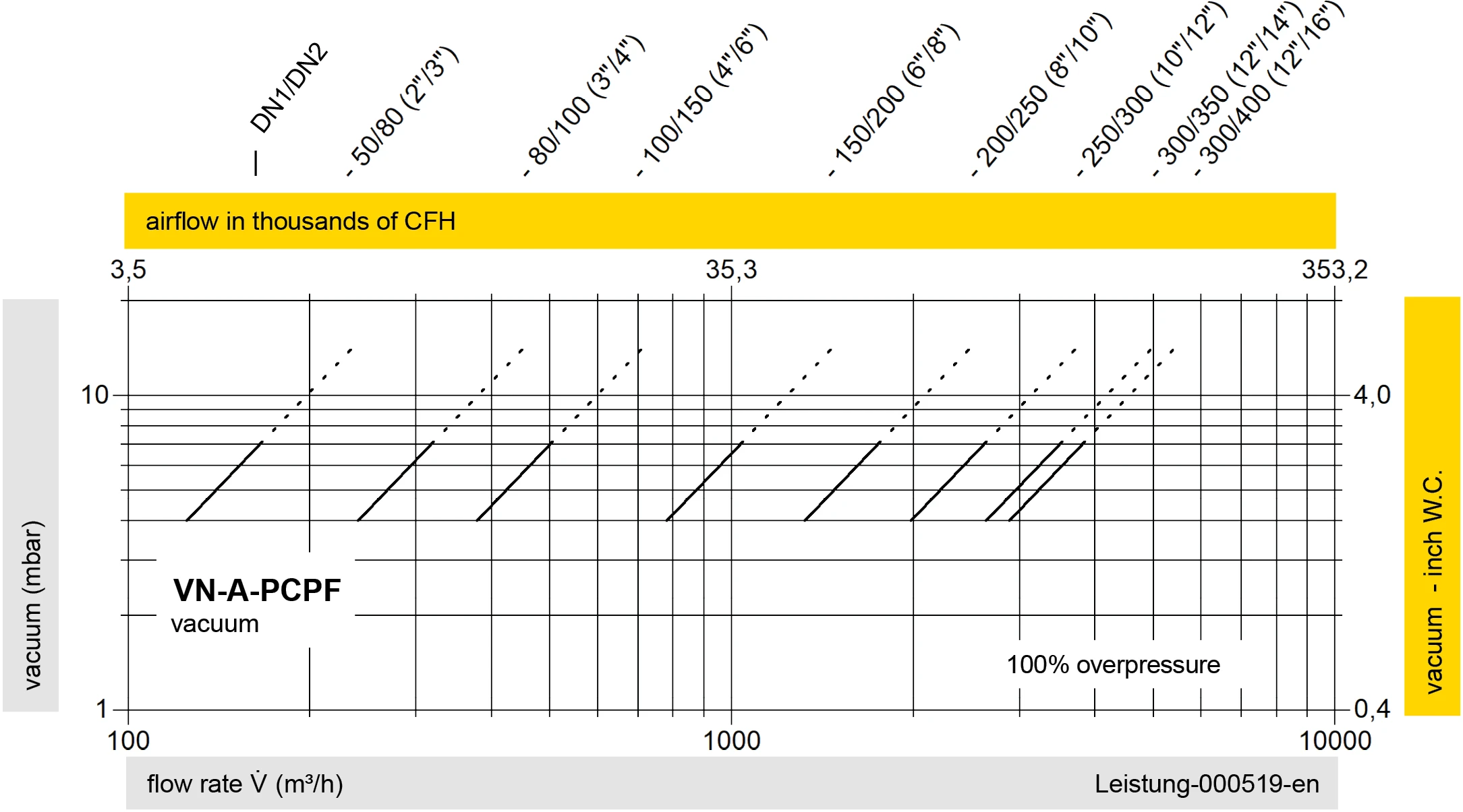
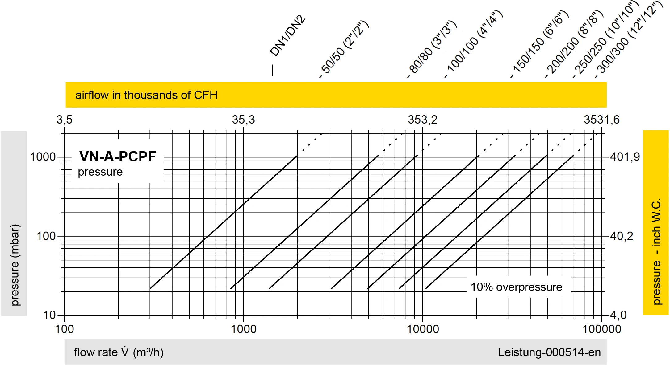
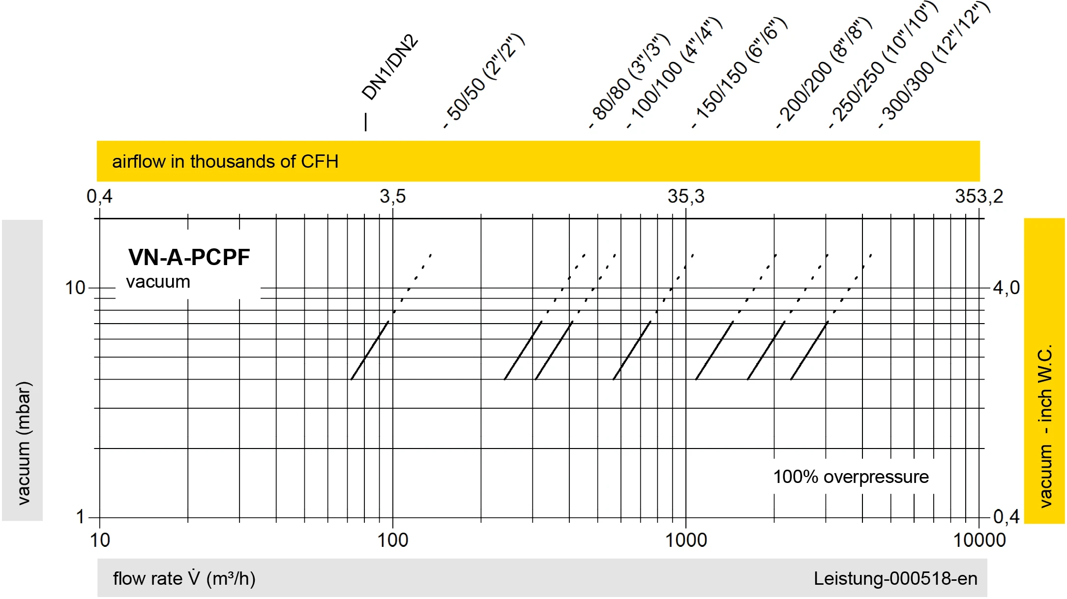
Este diagrama de vazão foi determinado em uma bancada de medição de vazão calibrada e certificada pela TÜV. A vazão V em m³/h se refere ao estado técnico padrão de ar, conforme ISO 6358 (20°C, 1bar). Para conversão em outras densidades e temperaturas, veja o cap. 1: Bases técnicas.
